Download
1 / 16
160 likes | 381 Views
Electromagnetic Induction. Chapter 21. Induced EMF. Galvonometer. Michael Faraday Hoped to induce a current Strong pulse when switch was opened or closed. Steady fields did not induce current Changing magnetic field produces an emf Electromagnetic Induction

E N D
Electromagnetic Induction Chapter 21
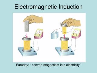
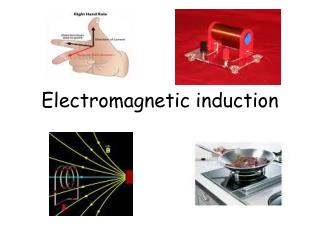
Induced EMF Galvonometer • Michael Faraday • Hoped to induce a current • Strong pulse when switch was opened or closed. • Steady fields did not induce current • Changing magnetic field produces an emf • Electromagnetic Induction • More rapid changes produces greater emf Iron Battery
Faraday’s Law of Induction • Magnetic Flux • Proportional to number of lines of magnetic field that passes through closed loop • ΦB = BAcosθ • ΦB = Magneitc Flux (Weber) • B = Magnetic Field (T) • A = Area (m2) • θ = Angle θ
Faraday’s Law of Induction • Coil spun in a magnetic field • E = -NΔΦB/Δt • E = induced emf (volts) • N = number of turns of wire • ΔΦB = change in magnetic flux (T) • Δt = time interval (seconds)
Lentz’s Law • Nature abhors a change in magnetic flux • The induced emf of the coil of wire will produce a magnetic field to oppose the original change in flux. • This is the reason for the negative sign in Faraday’s Law of Induction. • 3 ways to generate an induced emf • Change the magnetic field • Change the area of the loop inside the magnetic field • Change the loops orientation with respect to the field
Example • A square coil of wire 5 cm on a side with 100 loops is positioned perpendicular to a uniform 0.6 T magnetic field. It is quickly pulled from the field and in 0.1 seconds, it drops to a point where the magnetic field is zero. The resistance of all the wire in the loop is 100 Ω. • Find the change in flux through the coil. • Find the emf and current induced in the coil. • What is the total energy dissipated? • What is the average force required to pull the loops from the field?
EMF Induced in a Moving Conductor • E = Blv • E = Induced emf (V) • B = Magnetic Field (T) • l = distance (m) • v = speed (m/s) l
Example • Does a moving airplane develop a dangerous emf? An airplane travels 1000 km/hr in the earth’s magnetic field (5E-5 T), and is nearly vertical to the path of the aircraft. If the wing tips are 70 m apart, what is the potential difference between the wing tips?
Changing Magnetic Flux and Electric Field • A changing magnetic field induces an electric field • Changing magnetic flux induces an emf • Changing magnetic flux produces a current • Applies to all regions of space, not just conductors • E = vB • E = Electric Field (N/C) • v = Speed (m/s) • B = Magnetic Field (T)
Example • Since blood contains charged ions, it acts like a small electrical current. If the current flows through a magnetic field, you can measure the emf produced by moving blood. If the blood vessel is 2 mm in diameter, the magnetic field is 0.08 T, and the measured emf is 0.10 mV, what is the velocity of the blood?
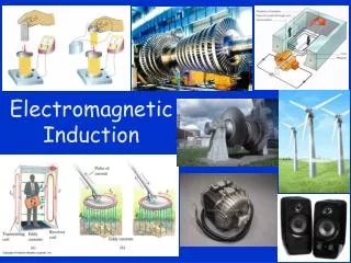
Electric Generators • Opposite of motors • Convert mechanical energy to electrical energy • Produces AC • The current changes direction with every turn • Emf produced also varies with every turn
Electric Generators • Rotating coil in an electric field • Emf = NBωAsin(ωt) • N = number of loops in coil • B = magnetic field (T) • ω = 2πf (f = frequency (Hz)) • A = area of the coil (m2)
Transformers • “Step up” vs “Step down” Transformers • Power companies • Primary • Coil to which the power is supplied • Secondary • Coil with the induced voltage
Transformers Cont. • Vs/Vp = Ns/Np • Vs = voltage of secondary coil • Vp = voltage of primary coil • Ns = number of loops in secondary coil • Np = number of loops in primary coil • Output Power = Input Power • Vs/Vp = Ip/Is
Example • A transformer for a radio reduces 120 V ac to 9 V ac. The secondary contains 30 turns and the radio draws 400 mA. • Calculate the number of turns in the primary. • Calculate the current in the primary. • Calculate the power transformed.
Example • An average of 120 kW of electric power is sent to a small town from a power plant 10 km away. The lines have a resistance (total) of 0.40 Ω. Calculate the power loss if the power is transmitted at 240 V and 2400 V.