Download
1 / 9
110 likes | 352 Views
Closed loop gain of noninverting op amp. (a). (b). Solving, we have V 0, max = 2.44 V. (c). Clipping occurs at output voltage of 12 V or input voltage of 3 V. Slew-Rate Limitation. As an example, assume we have a waveform,.

E N D
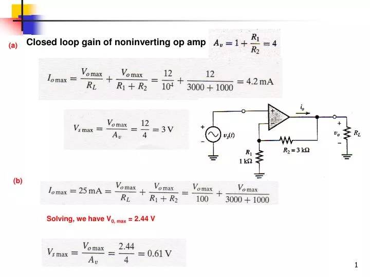
Closed loop gain of noninverting op amp (a) (b) Solving, we have V0, max = 2.44 V
(c) Clipping occurs at output voltage of 12 V or input voltage of 3 V
Slew-Rate Limitation As an example, assume we have a waveform, and we have to determine the output of the op-amp having a slew rate of 0.5 V/s
Full-Power Bandwidth The o/p voltage is: Taking derivative, we have: The maximum rate of the o/p voltage change is then equal to the slew rate: Thus the full-power bandwidth is: Thus, and undistorted full-amplitude sinusoidal voltage is possible only for frequencies less than fFP. If fFP is to be increased, then V0max must be reduced. Note that the output voltage is limited by 3 factors: (i) current limit, (ii) voltage limit, and (iii) frequency limit. All the limits need to be considered to determine the minimum voltage that can be amplified without distortion.
DC Imperfections: Input bias current: Input offset current:
Diode Characteristics iD = I0 exp(qV/kT – 1)
Small-signal Diodes A zener diode is used to limit voltages in circuits
Load line analysis Load line equation: Note that the equation can be solved if we know the voltage drop across the diode, which needs to be assumed, or given to you. Otherwise you will have to write the diode equation, which is non-linear, to obtain an exact solution.