Download
1 / 17
170 likes | 282 Views
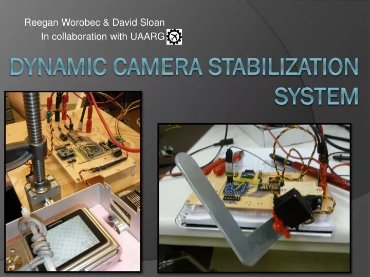
Reegan Worobec & David Sloan In collaboration with UAARG. Dynamic CAMERA STABILIZATION SYSTEM. WHAT IS IT?. WHAT IS IT?. An additional system intended to enhance the image processing capabilities of UAARGs UAV

E N D
ReeganWorobec & David Sloan In collaboration with UAARG Dynamic CAMERA STABILIZATION SYSTEM
WHAT IS IT? • An additional system intended to enhance the image processing capabilities of UAARGs UAV • A dynamic stability controller that updates its position in real time based on aircraft pitch and roll • Has the potential to track ground targets given their GPS coordinates
WHAT DOES IT DO? • Stabilizes a camera platform relative to ground independent of aircraft pitch and roll • Gathers sensor data from an onboard GPS and IMU (Inertial Measurement Unit) and stabilizes a camera platform by means of a pair of servo motors
OUR GOAL • Develop a system utilizing an FPGA • Keep platform stabilized • Read GPS data, send positional instructions to servo motors to adjust platform • GPS point tracking • Set camera angle at fixed location as opposed to relative ground plane
HOW DOES IT DO THIS? • The IMU takes measurements at a rate of 50Hz and calculates required servo positions • This information is then forwarded to the PWM controller to update the servo motor positions • It constantly polls for these updates, sending speed calibration data from the GPS to the IMU, and adjusts camera angle
HOW DOES IT DO THIS? (con’t) • Essential Matrix math • Normalize input vectors (frame orientation, and gimble orientation) • Project onto the frame servo’s rotational plane • Calculate first servo rotation • Transform frame orientation with new servo position • Project onto the second servo’s rotational plane • Calculate second servo rotation and update servo positions • GPS parsing* • Reads in NMEA sentences and parses for relevant information *Function completed in a desktop environment but not implemented in demo project
THE FPGA • The initial design utilized an FPGA as a reconfigurable microcontroller • Communicates with Inertial Measurement Unit (IMU), GPS, Flight Computer, and two servo motors • Sends information to servos via PWM controllers
INTERRUPT CONTROLLER OUT <= IN1 or IN2 or IN3 or IN4
GPS INVOLVEMENT • GPS information is fed through a UART connection as a continuous stream • We have parsing routines written to extract vital information we need for the microcontroller • Fix (Latitude/Longitude) converted to radians • Altitude [m] • Speed [m/s] • Speed bearing (direction of travel) • NMEA sentence: • $GPGGA,123519,4807.038,N,01131.000,E,1,08,0.9,545.4,M,46.9,M,,*47
OBSTACLES • Difficult development environment to interface our components • Unfamiliar environment to create custom hardware • Numerous operating issues with some of our components • Two IMU chips became unusable • one DOA, and a second spontaneously shorted • FPGA breakout board came with pins un-soldered