Download
1 / 22
490 likes | 2.07k Views
Time Delay Valve & Sequence Control Systems. Pneumatics – Module 7. Objectives. Demonstrate an understanding of the pneumatic time element. Demonstrate an understanding of the different types of time delay valves . Identify the symbol, and design of normally closed time delay valve.

E N D
Time Delay Valve & Sequence Control Systems Pneumatics – Module 7
Objectives • Demonstrate an understanding of the pneumatic time element. • Demonstrate an understanding of the different types of time delay valves. • Identify the symbol, and design of normally closed time delay valve. • Explain the function and principle of operation of normally closed time delay valve. • Identify the main parts of the time delay valve. • Draw a pneumatic circuit diagram that consists of a time delay valve, normally closed. • Simulate pneumatic circuit that consists of a time delay valve using Fluid SIM software. • Build a pneumatic circuit that consists of a time delay valve as per specific requirements. • Explain the the main types of displacement diagrams. • Draw a displacement step diagram for a given sequence of operation. • Draw a circuit diagram from a given sequence of operation.
Time delay valve • Pneumatic time elements can be formed very simply from combinations of three valves: • Directional control valve • Throttle valve • Reservoirs.
Function of the Time Delay Valve • Time delay valve is used to delay the output signal. • The time delay valve is actuated by a pneumatic signal through the tank after a preset time delay has elapsed. • Then returned to the normal position via return spring when the signal is terminated.
Symbols Time Delay Valve N/C Time Delay Valve N/O
Design • The time delay valve is a combination of a 3/2 way valve, one way flow control valve and air reservoir. • The 3/2 way valve can be normally open or normally closed. The delay time is generally ranging between (0-300) seconds for both types of valves (normally opened and normally closed). • By using additional reservoirs, the delaying time can be extended. • The type of the time delay valve whether normally opened or normally closed is determined according to the type of the 3/2 way valve if it is N/O or N/C.
Design 3/2 way valve N/C 3/2 way valve N/O
Principle of operation • The following operational principle applies for a time delay valve in normally closed position. • The compressed air is supplied to the valve at connection 1. The control air flows into the valve at 12 through a one way flow control valve and depending on the setting of the throttling screw, a greater or lesser amount of air flows per unit of time into the air reservoir, when the necessary control pressure has built up in the air reservoir, the pilot control of the 3/2 way valve is moved downwards. This blocks the passage from 2 to 3. The valve disc is lifted from its seat and thus air can flow from1 to 2 . • The time required for pressure to build up in the air reservoir is equal to the control time of the valve.
Principle of operation • Un-actuated Position • Actuated Position
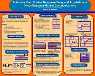
Practical task 1 • A double acting cylinder is used to press glued components together. Upon operation of a push button, the clamping cylinder extends. Once the fully advanced position is reached, the cylinder is to remain for a time of T = 6 seconds and then retract to the initial position automatically. The cylinder retraction is to be adjustable. A new start cycle is only possible after the cylinder has fully retracted.
Solution description • The limit switch 1S2 must be actuated as a start condition. And by pressing the push button switch 1 S1, two signals will reach the two pressure valve 1 V1, which in turn will pass the pressure signal to port 14 of the 5/2 way valve 1V3. The valve 1V3 reverses resulting in advancing the piston rod of the cylinder 1A with a specific speed according to the setting of the one way flow control valve 1 V4. • When the cylinder reaches the forward end position, it will activate the limit switch 1S3. The air reservoir of the time delay valve starts filling up, and after the adjusted time elapsed, the valve 1V2 will pass the pressure signal to port 12 of the valve 1V3. The valve 1V3 reverses, and the piston rod retracts to the initial position with adjusted speed determined by the one way flow control valve 1V5.
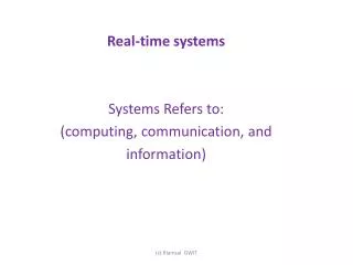
Introduction to Sequence Control Systems • A control system with compulsory stepped operation where switching from one step to the next in the program is dependent upon certain conditions being satisfied. • In particular, the programming of jumps, loops, branching, etc. is possible.
Sequence Control Time Dependent S.C. Process Dependent S.C. • A sequence control where the switching conditions are dependent only on time. • Step enabling conditions are generated via timers, or cam-shaft controllers with constant speed. • A sequence control system where the switching conditions are dependent only on signals from the system being controlled. Step-diagram control is a form of process-dependent sequence control; the step enabling conditions depend purely on the stroke-dependent signals of the controlled system.
Control of Multiple Actuators • In the case of multiple cylinder circuits, a clear definition of the problem is important. The representation of the desired motion of all actuators is described using the displacement-step diagram. The special conditions for the start of the sequence must also be defined. • If the motion diagram and auxiliary conditions have been clearly defined, drawing of the circuit diagram can commence. The circuit diagram should be designed according to the guidelines, in order for a circuit to operate, it is essential to avoid overlapping signals. • By an overlapping signal, we understand signals applied simultaneously at the two control ports of a double pilot valve. The following valves can be used to eliminate signal overlap: roller lever valves with idle return or toggle lever valves, time delay valves, reversing valves or sequencers.
Displacement Step Diagram • The displacement step diagram and the displacement-time diagram represent the operating sequence of the actuators, the displacement is recorded in relation to the sequence step.
Displacement Step Diagram • If a control system incorporates a number of actuators, they are shown in the same way and are drawn one below the other. Their interrelation can be seen by comparing the steps. • There are two cylinders 1A and 2A. In step 1 cylinder 1A extends and then cylinder 2A extends in step 2. In step 3 cylinder 1A retracts and in step 4 cylinder 2A retracts. Step number 5 is equivalent to step 1.
Displacement Time Diagram • In the case of a displacement-time diagram, the displacement is plotted in relation to the time
Example 1 • Find the sequence of operation for the given displacement step diagram A+A-B+B-C+C-
Example 2 • Draw the displacement step diagram for the following sequence of operation A+B+B-A-C+C-