Download
1 / 72
1.07k likes | 2.13k Views
CARDIAC CT BASIC PRINCIPLES AND CT CAG. DR RAJESH K F. Cardiac CT and CCTA has emerged as promising noninvasive imaging modality for coronary artery and cardiac structural and functional evaluation. F ormation of CT image Three phase process Scanning phase -scan data

E N D
CARDIAC CT BASIC PRINCIPLES AND CT CAG • DR RAJESH K F
Cardiac CT and CCTA has emerged as promising noninvasive imaging modality for coronary artery and cardiac structural and functional evaluation
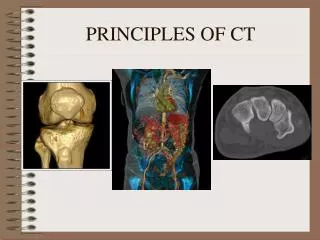
Formation of CT image • Three phase process • Scanning phase -scan data • Reconstruction phase - processes acquired data and forms digital image(pixels) • Digital to analog conversion phase - Visible and displayed analog image (shades of gray-Hounsfield units)
Sequential mode • First scanning mode • Scan and step • Prospective triggered • One complete scan around body while body is not moving Spiral or helical scanning • Retrospective gating • Body moved continuously as x-ray beam scan around • Higher radiation dose
SDCT • Single detector row helical/spiral CT MDCT • Electronically acquire multiple adjacent sections simultaneously
Full Scan Reconstruction • Full rotation (3600) reconstruct one image Half-scan reconstruction • Commonly used in cardiac CT • Data from 1800 sweep • Temporal resolution- half gantry rotation time Multisegmentreconstruction • For multidetector systems • Use <1800 rotation
RECENT ADVANCES Temporal resolution • Gantry rotation time decreased • Temporal resolution correspond to half rotation time • Maximum gantry rotation time - 270 to 330 msec • Temporal resolution is approximately 83 to 165 msec - half-scan reconstruction techniques • Image acquisition or reconstruction during periods of limited cardiac motion (end systole to mid-late diastole)
RECENT ADVANCES Spatial resolution • Decreased slice collimation (thickness) • Approximately 0.5 mm3 Strengthened X-ray tubes - Reduce image noise Multislice • Data in more slices simultaneously • From 4 to 64 to 320 per rotation • Decreases overall duration of data acquisition, breath hold duration and amount of contrast
TECHNOLOGY OF CARDIAC CT 64-slice scanners • High temporal and spatial resolution • Gantry rotation times of 420 ms or shorter • Spatial resolution of 0.4 by 0.4 by 0.4 mm • “state-of-the-art” equipment for CTA • Breath hold is 6 to 12 s
256 slice CT • Spatial and temporal resolution remain unchanged • Approx 0.5-mm collimation • Increase volume coverage (number of slices) • Image heart in single beat • Less vulnerable to arrhythmia
EVOLUTION OF COMMON MULTIDETECTOR COMPUTED TOMOGRAPHY TECHNICAL PARAMETERS
Dual-source CT • Number of slices - 64 • 2 X-ray tubes and detectors in single gantry at 90° • One-quarter rotation of gantry collect data from 180° of projections • Temporal resolution is twice of single X-ray tube and detector • Reduce motion artifact
CARDIAC COMPUTED TOMOGRAPHY Thin-slice cardiac CT reconstructions • Displayed in any imaging plane
Multiplanar imaging • Oblique planar views • Images displayed in orthogonal planes (axial, coronal, sagittal) or nonstandard planes • Analysis of cardiac chambers
Maximal intensity projection • Thick-slice projections • Pixel within slab volume with highest Hounsfield number is viewed • Ability to view more structures in single planar view • Can obscure details when high-density structures are present (coronary artery calcium)
Curved multiplanar reformations • Curved structures can be viewed in planar oblique multiplanar reformats • Can be used to evaluate entire coronary tree in one view
Volume rendered reconstructions • Useful for revealing general structural relationships but not for viewing details of coronary anatomy
CORONARY ARTERY CALCIUM SCANNING • Non-contrast study • Refine clinically predicted risk of CHD beyond that predicted by standard cardiac risk factors • Used in asymptomatic patients • Coronary calcium Present in direct proportion to extent of atherosclerosis • Minority (20%) of plaque is calcified
3 mm non overlapping thick tomographic slices • Average about 50–60 slices • From coronary artery ostia to inferior wall of heart • Calcium score of every calcification in each coronary artery for all of tomographic slices is summed
CALCIUM VOLUME SCORING Area = 8 mm2 Peak CT = 290 Score = 8 x 2 = 16 Area = 15 mm2 Peak CT = 450 Score = 15 x 4 = 60 AGATSTON SCORE = Sum Hn x-factor (Agatston Scoring) 130-199 1 200-299 2 300-399 3 >400 4
CALCIUM SCALE 4 calcium score categories Calcium score correlates directly with risk of events and likelihood of obstructive CAD Interscanvariability of 10% to 20%
Coronary calcium presence and extent are dependent on age, gender, ethnicity, and standard cardiac risk factors • Calcium scores are higher for age and male gender among whites
Data from 13 studies (75,000 patients) during 4 years - calcium score of 0 is associated with a very high event-free probability (99.9% per year)
Five-Year Mortality Rates in Framingham Risk Subsets by Coronary Calcium Score * *p<0.001 * * Shaw et al. Radiology 2003; 228:826-833
DETECTION OF CAD/RISK ASSESSMENT IN ASYMPTOMATIC INDIVIDUALS WITHOUT KNOWN CAD
VENTRICULAR MORPHOLOGY AND FUNCTION • Helical scan • Provide CT data from systole and diastole • Can be displayed in cine-loop format • Estimation of RVEF, LVEF, volumes and RWMA • EF highly accurate
Myocardial morphology - wall thinning, calcification or fatty replacement (negative HU densities) • Atrial morphology and volume
VALVULAR MORPHOLOGY AND FUNCTION • Anatomic evaluation of cardiac valves and their motion • Both native and prosthetic • Lack of physiologic valve flow evaluation • Prosthetic valve malfunction- size mismatch, tissue ingrowth, and valve thrombosis
Severe AR- malcoaptation of leaflets >0.75 cm2 • AS- extent of valve calcification and planimetry • Planimetryequalent to other invasive and noninvasive methods • Aortic valve calcification is directly related to valve area and quantitated by area-density methods
CARDIAC MASSES • Less information concerning tissue type than CMR • Lipomas-low CT numbers (< 50 HU) • Cysts – water like density (0 to 10 HU) • Intracardiacthrombi – (20 to 90 HU) • Density values overlap with myocardium • Identify thrombi in LAA • Poor enhancement of LAA- false-positive result common
PERICARDIUM • Embedded in epicardial and pericardial fat-can be delineated in CT • Normal thickness-1to 2mm • Can clearly delineate pericardial calcification
CORONARY CT ANGIOGRAPHY • Visualization of coronary arteries and lumen • Excellent tool to investigate coronary artery anomalies Problems • Rapid motion • Small dimensions of coronary arteries • Temporal and spatial resolution of CT
DATA ACQUISITION FOR CORONARY CTA Lower heart rate to 60 beats/min - Oral or intravenous BBs • Metoprolol25 to 100 mg orally 1 hour before or IV 5 mg rpt doses Dilate coronary arteries • Sublingual nitrates immediately before scanning • Nitroglycerin 400 to 800 Microgm Breath hold of 6 to 20 s • Depend on scanner generation and dimensions of heart • 50 to 120 ml of contrast IV
RADIATION EXPOSURE (effective dose) • 3 to 15 mSv, depending on scan protocol • ECG-correlated tube current modulation • Reduction of tube current in systole • Can reduce radiation exposure by 30% to 50%
TYPICAL DATASET AS ACQUIRED BY CTA AFTER INTRAVENOUS CONTRAST AGENT
2D image reconstruction • Maximum intensity projections • Facilitate data interpretation • Only maximal density values at each point in 3-D volume are displayed
2D image reconstruction • Curved multiplanarreconstruction • Evaluate entire coronary tree in one view
3 Dimensional display • Visually pleasing • Rarely helpful to evaluate data
IMAGE QUALITY AND ARTIFACTS Motion artifact • Irregular and fast HR • Respiration • Limit temporal and spatial resolution • Blurr contours of coronaries RCA - most frequently affected
Partial volume effect • e.g., metal, bone , calcifications • Appear bright on image • Lead to overestimation of dimensions of high-intensity objects • Accuracy for detection of coronary stenoses is lower
Streaks and low-density artifacts • Adjacent to regions of very high CT density • e.g., metal or calcium
DETECTION OF CORONARY ARTERY STENOSES 64-row CTA • Overall accuracy • Sensitivity of 87% to 99% • Specificity of 93% to 96% • NPV -93 to 100% • ~4% uninterpretable • Specificity reduced in calcium scores > 400 to 1000 or obesity (excess image noise) • Best for ostialand first centimeter lesions
PROSPECTIVE MULTICENTER STUDIES FOR DIAGNOSTIC PERFORMANCE OF CCTA Most studies are limited by selection of patients optimized for cardiac CT and analysis involves only more proximal coronary segments down to 1.5 mm
Compared with grading by CAG, CT CAG stenosis severity tends to be worse and correlation is 0.5-0.6 • Correlates very well with IVUS (better visualization of arterial wall) • >50% stenosis on cardiac CT has 30% to 50% likelihood of demonstrable ischemia on MPI
DIAGNOSTIC ACCURACY OF CCTA FOR MYOCARDIAL ISCHEMIA • Identification of obstructive CAD did not successfully identify individuals with abnormal MPS • Measures of perpatient coronary artery plaque burden, proximity, and location predictive of identifying individuals with abnormal MPS
CTA Limitations • Rapid (>80 bpm) and irregular HR • High calcium scores (>800-1000) • Stents • Contrast requirement • Small vessels, distal vessels (<1.5 mm) and collaterals • Obese • Radiation exposure
RISK STRATIFICATION BY CCTA IN INDIVIDUALS WITH STABLE CHEST PAIN