Download
1 / 39
390 likes | 398 Views
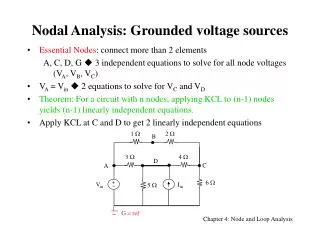
Neutral Switching of Grounded Sources. Dave Loucks, PE. Switching Methods. 3-Pole 3-Pole with Overlapping Neutral 4-Pole. Issues. Ground Discrimination Transient Voltages. Ground Discrimination. Identify source(s) feeding ground fault and clear Two scenarios:

E N D
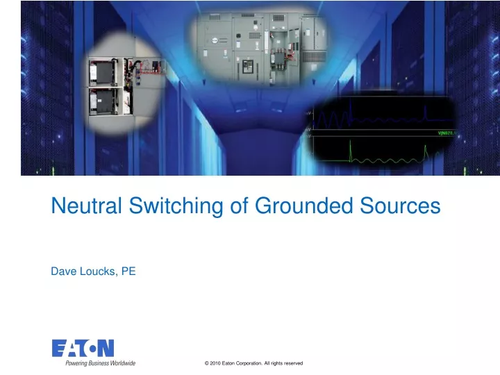
Neutral Switching of Grounded Sources Dave Loucks, PE
Switching Methods • 3-Pole • 3-Pole with Overlapping Neutral • 4-Pole
Issues • Ground Discrimination • Transient Voltages
Ground Discrimination • Identify source(s) feeding ground fault and clear • Two scenarios: • Single Ground: Non-Separately Derived • Multiple Ground: Separately Derived
Single Ground: Non-Separately Derived CT 1output = IF CT 2output = 0 Source 1 Source 2 IF IF IF IF IF • Issue • Ungrounded sources cannot be detected as sources of ground current using CT at source.
A Solution: Non-Separately Derived Reliable Tripping Power GF Relay S1A S1T S2A S2T Source 1 Source 2 IF IF IF IF IF
Separately Derived System: 3-Pole CT 1output = IF - 1/2IF = 1/2IF CT 2output = 1/2IF Source 1 Source 2 1/2 IF 1/2 IF 1/2 IF IF IF 1/2 IF 1/2 IF • Issue • Multiple grounded sources with unswitched neutral share ground current between each source
A Solution: Separately Derived CT 1output = IF CT 2output = 0 Source 1 Source 2 IF IF • Solution • Switch neutral to break “cheat” path for ground current.
Separately Derived – Overlapping Neutral CT 1output = IF - 1/2IF = 1/2IF CT 2output = 1/2IF • During the transition, this design looks the same as a 3-Pole device • If a GF were to occur during this transition, same problems as with 3-Pole switching Source 1 Source 2 1/2 IF 1/2 IF 1/2 IF IF IF 1/2 IF 1/2 IF
Transients VL i + - • So maybe an overlapping neutral has some problems with GF discrimination, but doesn’t 4-pole switching the neutral create transient overvoltages on the neutral? • After all, whenever current through an inductive circuit is interrupted, you have the potential for transient overvoltage. • We can calculated the magnitude of voltage of this transient from:
Can We Model Transients Accurately? • To prove our model was accurate, we would need to compare our calculated transients on a switched neutral with measured transients from an actual lab experiment • If our modeled values are equal to or greater than the values measured in the lab, then we could have confidence in our model • After all, if our model estimates higher transients than what we measure in the lab, we can call our model “conservative” since actual transients will not be higher than our model.
Lab Test versus SPICE Model Equiv. SPICE Model • 848.428 VL-L peak • Z = 0.06 • 60 Hz • X/R = 1.77 • R = 0.0295137 • XL= 0.0522393 • @ 60 HzL = 0.1385 mH Lab Test: • 600 VL-L • 10 kA rms available • 60 Hz • 49.1% PF • For test, both systems are ungrounded
Problem: We Still Have an Unknown • While we know L, di (change of current) … • … we don’t know dt (time to change current) • How fast does a switched neutral operate? • The faster it operates, the smaller the value of dt • The smaller the value of dt, the higher VL
Progression of Arcing Contact Time 1.1 ms Time 1.2 ms Time 5.5 ms Measured: Time = 0 Total Arc Extinguishing Time 8.2 ms
LT-SPICE Model Note: “ungrounded” means capacitively grounded
Actual Lab Test Note: 530V / 848V = 63% ~ 530 V
Model Matches Very Closely Note: 801V / 848V = 94% • In fact, our model is “conservative” since model predicts higher transient than lab test • Raises confidence that transients will be less Fault current ~ 801 V ~ 530 V Arcing voltage Current zero, arc extinguishes System voltage
Increase Size of Model • Now that we have our switching model, we can change our source and see how the transients change • New Test: • Source 1 – Utility • 1500 kVA transformer, Z = 5.75%, 480Y/277 Vrms, 60 Hz, X/R = 6.6 (IFL = 1804 Arms, ISC = 31377 Arms • Source 2 – Utility • Ratings same as Source 1 • Load • 600 Arms, 80% PF (X/R = 0.75)
Schematic Model • Refer to Figure 21, page 20 and pages 14 - 19 for calculation of these values
GF and Transient Tests • Non-separately derived (NSD) sources • Test 1: Open transition 3-pole switching (Figure 21) • Separately derived (SD) sources • Test 2: Open transition 3-pole switching • Test 3: Open transition 4-pole switching • Test 4: Open transition phase 3-pole, closed transition neutral (overlapping) switching
Test 1: NSD 3-pole switching (page 20) Reliable Tripping Power GF Relay S1A S1T S2A S2T Source 1 Source 2 IF IF IF IF IF • NSD means only one source grounded • Assume GF system connected as shown in Figure 5 (page 4), so no GF discrimination problem • 3-Pole switching means no neutral switching • no neutral transient
Test 2: SD 3-pole switching (Page 21-22) Source 1 Source 2 0.001847 0.001847 24.01 H 24.01 H 0.001847 24.01 H 0.001847 24.01 H IF IF 0.5 0.5 • SD means multiple grounded sources • Unswitched neutral means cheat path allows GF currents to flow even through sources with 3-pole switching device open
Test 2: SD 3-pole switching (Page 21-22) • Measured GF current is only fraction of actual • … but that isn’t the only problem … Actual GF current magnitude (1472 A peak)( 1041 A rms) GF current measured at source 1 zero-sequence CT (671.8 A peak)(475 A rms)
Test 2: SD 3-pole switching (Page 21-22) • GF current is detected as flowing through de-energized source! A, B and C phase current = 0 Neutral current = 733 A peak (533 A rms)
Switch Neutral • These problems are well known and are the reasons why we switch the neutral of separately derived sources • Two main methods: • 4-Pole • 3-Pole with Overlapping Neutral Switching • 3-Pole with Customer GF wiring
Transients • What about the reported transients? • What does the our model say? • Equation of transient says it will be proportional to the current flowing in the neutral at the time of the interruption • How much current flows in the neutral?
Neutral Current • Balanced Load • Unbalanced Load
Test 3: SD 4-Pole Balanced Load • Very low or no current flows in neutral • Modeled transient less than a 0.1 volt 0.1 V peak Voltage across Source 2 neutral 0.1 V peak Voltage across Source 1 neutral
Test 3: SD 4-Pole Unbalanced Load • Worst case is full phase current • Modeled transient less than phase voltage • Peak phase voltage: 277 Vrms*1.414 = 391 Vpeak < 300 V peak Voltage across Source 2 neutral < 300 V peak Voltage across Source 1 neutral
Unbalanced Load • Need to confirm that GF current correctly isolates ground currents to only active sources • Notice that regardless of which source is switched, only the active source detects GF current Source 2 detected GF current 100 ms open transition Source 1 detected GF current Total GF current flowing
4-Pole “Non-Issues” • Worst case unbalanced load switching means neutral must switch load current • But it is a fully rated pole • Worst case, it must switch peak phase voltage • But it is a fully rated pole • Absolute worst case is that it might need to interrupt fault current • But it is already a fully rated, fault duty interrupting pole
Test 4: SD 3-pole OL neutral (Page 25-26) • Any transient from the switching only occurs if there is current flowing through the de-energized source. • That can occur during a GF • Also, the problem is that a 3-pole OL switch is essentially a 3-pole switch during the switching time, so it suffers from the same problems of GF discrimination
Test 4: SD 3-pole OL neutral (Page 25-26) • Here a GF occurs during transition, but fault current is divided between sources • Reduces current to relay that supposed to see it • Nuisance tripping of relay that isn’t supposed to see it ~ 1/2 peak GF current at source feeding fault (Source 2) Balance of GF current flowing through overlapping neutral Actual GF current increases higher than with 4-pole switching!
Summary • 3-Pole with OL neutral does not accurately measure GF currents • 4-Pole accurately measures GF currents • 4-Pole does not generate voltages that exceed normal phase voltage • 3-Pole with OL neutral could create a transient during a GF • 4-Pole does not increase magnitude of GF • 3-Pole with OL neutral can increase magnitude of GF
References • See page 28 of paper • LT Spice is available free of charge from http://www.linear.com/ltspice • SPICE models used in this paper as well as this PowerPoint can be downloaded from http://pps2.com/files/xfer/spice