Download
1 / 20
210 likes | 413 Views
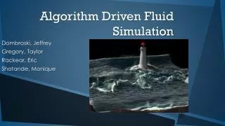
Direct Numerical Simulation of Fluid Driven Fracturing Events with Application to Carbon Sequestration Joseph Morris and Scott Johnson. Lawrence Livermore National Laboratory, P. O. Box 808, Livermore, CA 94551. LLNL-PRES-404894 .

E N D
Direct Numerical Simulation of Fluid Driven Fracturing Events with Application to Carbon Sequestration Joseph Morris and Scott Johnson Lawrence Livermore National Laboratory, P. O. Box 808, Livermore, CA 94551 LLNL-PRES-404894 This work performed under the auspices of the U.S. Department of Energy by Lawrence Livermore National Laboratory under Contract DE-AC52-07NA27344
Geomechanical response represents a primary source of risk to successful CO2 storage • Injection of enormous volumes of CO2 will cause • Increased pore pressures • Large scale reservoir deformation • These mechanisms alter stresses in • Caprocks • Pre-existing fractures and faults High porosity/ permeability reservoir E.g: Saline aquifer Low permeability caprock E.g: Shale
Caprock seal failure mechanisms • Need to establish what CO2 pressures will lead to risk of caprock failure under reservoir conditions • We are investigating three sources of risk: • Creation of new fractures • Activation of faults • Activation of fracture networks
Livermore Distinct Element Code (LDEC):Key Features and Capabilities • Fully 3-D fully coupled fluid-solid solver • Distinct Element Method (DEM) Module • Rock mass represented by arbitrarily shaped polyhedral blocks • Can accommodate realistic joint-sets • Empirical joint models – slip, hysteresis, dilation • Block representations: • Rigid / Uniform deformation (“Cosserat blocks”) / Finite elements • All block types support: • Dynamic contact detection • Dynamic fracture/fragmentation • Smooth Particle Hydrodynamics (SPH) Module • Fully coupled fluid dynamics • Flow network solver • Fully coupled fluid dynamics confined within fractures • Fully parallelized: Demonstrated on up to 8000 CPUs • Will be available under license from LLNL shortly
Caprock seal failure mechanisms • Need to establish what CO2 pressures will lead to risk of caprock failure under reservoir conditions • We are investigating three sources of risk: • Creation of new fractures • Activation of faults • Activation of fracture networks
Dynamic Fracture:Experiment with a notched plate • It is observed that as loading rate is increased, crack velocity is limited and falls short of the Rayleigh wavespeed [From Zhou, F., Molinari, J.-F., and T. Shioya, 2005]
Dynamic Fracture: Cohesive Elements • Nodes split when specified fracture criteria are met • Tensile • Shear • Introduce cohesive element between new nodes: • Ensures correct energy is dissipated (proportional to surface created) • Reduces mesh size dependence • Currently fracture must follow existing element boundaries
Block, Rubin, Morris and Berryman (2008) Dynamic Fracture: LDEC Cohesive Elements
We have recently added a network flow capability to support simulation of hydraulic fracture LDEC: • Add coupling with matrix geomechanical response Koudina et. al. (1998): • Flow through fractures on an unstructured mesh • Lacks coupled geomechanics • Triangular finite volumes with element-centered pressure • Fully coupled with solid elements to model hydrofracture • Triangular finite volumes with node-centered pressure
y: 4 cm x: 6 cm Initial fracture z: 6 cm LDEC Demonstration of hydraulic fracture • Pressurized crack propagates into the rock • Prediction of caprock and reservoir rock integrity • Characterization of seismic sources for far-field detection and interpretation
Caprock seal failure mechanisms • Need to establish what CO2 pressures will lead to risk of caprock failure under reservoir conditions • We are investigating three sources of risk: • Creation of new fractures • Activation of faults • Activation of fracture networks
Simulation of fault activation due to fluid injection:Application to Teapot Dome Full geomechanics with LDEC Facets of fault considered in isolation • Change in pore pressure that will result in activation of given location on S1 fault (similar to Chiaramonte et al, 2007). • Plot of fault area activated as a function of increase in pore pressure on fault surface
Caprock seal failure mechanisms • Need to establish what CO2 pressures will lead to risk of caprock failure under reservoir conditions • We are investigating three sources of risk: • Creation of new fractures • Activation of faults • Activation of fracture networks Caprock/reservoir
Simulation of injection into a heavily fractured reservoir • Distinct element model with explicit fracture elements modeled between arbitrary polyhedral blocks Fracture network Delta-Pore pressure field • Small test problem: • 13 thousand, variably oriented fractures • Anisotropic stress field: east = overburden,north = 0.6 overburden
Simulation of injection into a heavily fractured reservoir • The proportion of joints of each orientation relative to North that have failed during fluid injection • Joints of all orientations fail due to redistribution of stress • Predominantly those initially experiencing shear stress • Provide predictions of permeability change • Predict energy release from fractures during injection
Conclusions • Caprock integrity represents a significant potential source of risk to successful geologic storage of CO2 • LDEC has demonstrated capabilities for predicting: • Fluid driven fracturing events • Activation of existing faults • Activation of existing networks of fractures • Moving forward: • Parameter studies to evaluate risk to CO2 containment • Funded to participate in large scale field projects • Other applications: • Unconventional gas/oil recovery
Extras… • Extras…
O(1 km) O(1 m) O(10 m) We are developing interfaces between LDEC and FRAC-HMC to span the scales of interest Reservoir Scale: Simulation/Measurement of insitu conditions during operation NUFT, partners in industry Individual Fracture scale: Simulation of activation and creation of caprock fractures LDEC Local fracture network scale: Simulation of consequent fracture network permeability and local stress change FRAC-HMC/LDEC
Simulation of fault activation due to fluid injection • Finite element model with fault modeled by material with shear strength dictated by prescribed coefficient of friction 5 km well 2 km 5 km reservoir Fault plane
Simulation of fault activation due to fluid injection • Slip on fault results in discontinuity in surface expression Mounding due to injection Slip on fault results inreduced displacement on other side of fault Injection source at 1500m depth