Download

1 / 17
180 likes | 357 Views
Modeling Component-based Software Systems with UML 2.0. George T. Edwards Jaiganesh Balasubramanian Arvind S. Krishna Vanderbilt University Nashville, TN 37203. Talk Outline. Introduction UML 1.x History & Shortcomings UML 2.0 Specification, Design Goals and Enhancements

E N D
Modeling Component-based Software Systems with UML 2.0 George T. Edwards Jaiganesh Balasubramanian Arvind S. Krishna Vanderbilt University Nashville, TN 37203
Talk Outline • Introduction • UML 1.x History & Shortcomings • UML 2.0 Specification, Design Goals and Enhancements • Case Study: The UML 2.0 Structure Packages • Composite Structure • Example: Collaboration Diagram • Component • Example: Component Assembly • Deployment • Example: Run-time Deployment
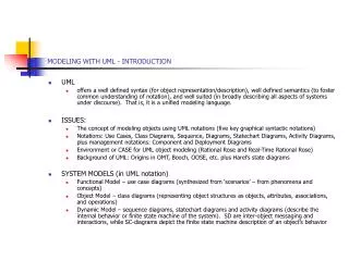
The Unified Modeling Language • UML is a suite of object-oriented modeling packages that can be used to describe the structure and behavior of engineering systems. • UML 1.0 was first standardized in 1996 to unify the Booch, Object Modeling Technique (OMT), and Object-Oriented Software Engineering (OOSE) methods. • UML 1.x gained widespread acceptance as the standard way to describe software architecture. • Over time, problems in the UML 1.x specification began to appear. • Excessive size and complexity. • Limited customizability. • Some unused, poorly-defined elements. • Inadequate support for components.
UML 2.0 Design Goals The UML 2.0 Request for Proposals laid out the following requirements: • Clarify the semantics of the generalization, dependency, and association relationships. • Support encapsulation and scalability in behavioral modeling, especially for state machines and interactions. • Remove restrictions on activity graph modeling due to the mapping to state machines. • Add data flow modeling. • Increase expressiveness of sequence diagrams. • Enable the modeling of structural patterns, such as component-based development. • The OMG has formulated an initiative called “Model-Driven Architecture” (MDA) • A framework for a set of standards in support of a model-centered style of development • Key characteristic of MDA: • The focus and principal products of software development are models. • Key design goal for UML 2.0: • Improve the conceptual foundations of UML to provide better support for MDA.
UML 2.0 Specification UML 2.0 is divided into four sub-specifications. • The infrastructure defines modeling primitives. • The superstructure defines user-level packages. • The diagram interchange allows the smooth exchange of UML-compliant models between software tools. • The OCL description defines a formal language for constructing expressions on UML models. The superstructure specification contains the structure and behavior packages that nearly everyone uses. The infrastructure specification exists to simplify the overall UML hierarchy and allow extensions.
UML 2.0 Structure Packages • Class contains sub-packages that define the basic structural modeling concepts of UML, particularly classes and their relationships. • Component contains artifacts for specifying software components, their interconnections and their implementations. • Composite Structure allows representation of the internal structure of classes using containment and hierarchies. • Deployment specifies a set of constructs that define the execution architecture of software systems. The UML 2.0 Superstructure defines four packages that successively depend on each other:
Composite Structure Diagrams (1/3) Composite Structures are run-time instances of classes collaborating via connections. Why model Composite Structures? • Allows representation of the internal structure of a class. • Can represent run-time behavior of objects by: • specifying interconnections and collaborations between class instances. • delegating operations to internally contained objects.
Composite Structure Diagrams (2/3) Composite Structure Diagrams extend the capabilities of Class Diagrams. Class Diagrams: • do not specify how internal parts are organized within a containing class. • have no direct means of specifying how interfaces of internal parts interact with environment.
Composite Structure Diagrams (3/3) Modeling Elements: • Parts & Connector models how internal instances are to be organized. • Port defines an interaction point between a class and its environment or a class and its contents. • Collaboration provides constructs for modeling roles played by connections.
… Modeling Components (1/4) Components are highly flexible and reusable software modules. • Have well-defined interfaces. • Run on generic application servers. • LOTS of other features that make them valuable software engineering artifacts. Why model components? • Generate “glue-code” that wires components together. • Configure component assemblies and underlying middleware.
Component Diagrams (2/4) UML 2.0 Components address the deficiencies of 1.x Components UML 1.x components: • required syntax that did not scale well… • Diagrams with many components were difficult to understand, manage, and maintain. • did not have the capability to precisely define interconnections and assemblies… • No ports for provided/required interfaces. • No composition of component packages.
Component Diagrams (3/4) Modeling Elements: • Basic Component extends Structured Class. • Packaging Component encapsulates other elements within a namespace. Both component types have two views: • External publicly visible properties and operations. • Provided and required interfaces as ports. • Wiring between components. • Internal private properties and realizing classifiers. • Delegation of port operations to contained class implementations.
Component Diagrams (4/4) Components interact with: • Interface specify the operations that the component implements as well as the operations that the component invokes. • Class specify the internal operation implementations. • Realization delegate interface operations to class implementations. • Port specify the connection points between component interfaces.
Deployment Diagrams (1/2) The Deployment Package specifies the execution environment for component-based software systems. • Comprises a set of constructs that can be used to represent the assignment of software artifacts to nodes. Why Model Deployments? • Gain fine-grained control over the mapping of logical constructs, such as components, onto physical resources such as CPUs. • Decouple platform-independent models from platform-specific models.
Deployment Diagrams (2/2) Modeling Elements: • Node represents hardware devices or software execution environments; connected through communication paths to create networks of systems. • Communication path an association between nodes through which they are able to exchange messages or signals. • Artifact represents a concrete element in the physical world that is a result of a software development process. • Deployment specification describes the configuration of artifacts deployed on the target nodes.
Concluding Remarks • UML 2.0 represents the next generation of engineering system and business process modeling. • New key features drive the evolutionary step towards the Model-driven Architecture. • Support for component-based development. • Interplay with CORBA Component Model. • Assembly, configuration, and deployment modeling. • Undoubtedly, engineers in all disciplines will become more and more dependent on standardized, semantically precise modeling paradigms. • UML will continue to evolve as requirements and challenges arise.