Download
1 / 32
330 likes | 495 Views
Diffraction and Imaging. Topics. Objective aperture selection BF/DF imaging Relationship of DP to image. BFP. stronger lens - shorter focal length. Image vs. Diffraction. Objective aperture selection. The BFP contains the DP (shows reciprocal space) and the objective aperture.

E N D
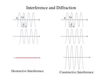
Topics • Objective aperture selection • BF/DF imaging • Relationship of DP to image
BFP stronger lens - shorter focal length Image vs. Diffraction
Objective aperture selection • The BFP contains the DP (shows reciprocal space) and the objective aperture. • Remember, small objects in real space become large in reciprocal space. • Larger objective apertures allow finer detail. • … but by allowing more of the scattered electrons to contribute to the image it has lower contrast.
No scattered electrons from hole Large aperture – lower contrast Small aperture – higher contrast Objective Aperture Size
BF/DF Aperture Position Dark Field Bright Field
What you see on screen On-axis Dark Field How do you center DF beam?
Not in Bragg condition! Tilt to +g If you move diffracted spot into center, it will disappear.
Still in Bragg condition! Tilt to -g If you move direct beam to +g spot, -g will light up.
DF imaging Dark Field
BF/DF selector Beam Tilts in DF mode DF controls
DF channel (memory) Beam Tilt Display DF page
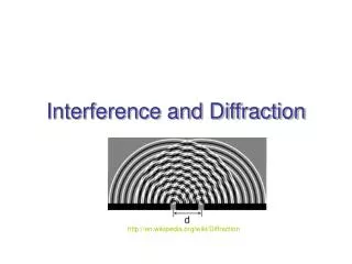
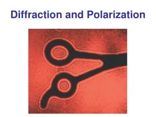
Crystallographic Imaging • TEM can give both image and crystallographic (diffraction) information. • To be useful, we need to relate the image to the diffraction pattern. • We can then mark crystallographic directions on our images.
Image Rotation • Lorentz force causes the electron to spiral through the lens. • The amount of spiral varies with the magnetic field. • Changing the field (lens strength) rotates the image.
sample 1st intermediate image DP under/over focus
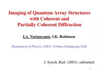
SA aperture MoO3 Crystal
(100) Underfocus DP
Camera Length Diffraction Focus Diffraction Focus
(100) MoO3 DP
34° CCW Rotation angle
Double Exposure Double Exposure
Rotation Angle • We usually work at fixed CL, measure from DP to image • Note sense of rotation (CW/CCW) • Work with film emulsion up. Be consistent.
Lab 5 • Sample: MoO3 crystals on lacy carbon • Tasks: BF/DF imaging, Rotation calibration • Investigate effects of obj. aperture size, on-axis vs. off-axis DF imaging, rotation of image w.r.t. DP