Download
1 / 27
350 likes | 656 Views
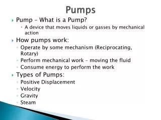
Pumps and Lift Stations. Background. Fluid Moving Equipment. Fluids are moved through flow systems using pumps, fans, blowers, and compressors. Such devices increase the mechanical energy of the fluid. The additional energy can be used to increase. Velocity (flow rate) Pressure Elevation.

E N D
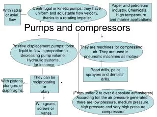
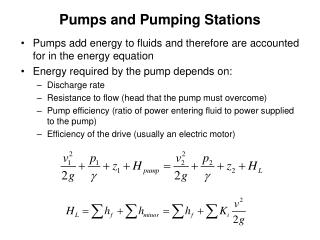
Background Fluid Moving Equipment Fluids are moved through flow systems using pumps, fans, blowers, and compressors. Such devices increase the mechanical energy of the fluid. The additional energy can be used to increase • Velocity (flow rate) • Pressure • Elevation
Why are most water towers 130 feet high? Because a column of water 2.31 ft high exerts a pressure of 1 psi, and most city water systems operate at 50 to 60 psi
destination source Static head Static Head Difference in height between source and destination Independent of flow Static head Flow
Friction Head Resistance to flow in pipe and fittings Depends on size, pipes, pipe fittings, flow rate, nature of liquid Proportional to square of flow rate Friction head Flow
Net Positive Suction Head The allowable limit to the suction head on a pump 33 - friction losses through the pipe, elbows, foot valves and other fittings on the suction side of the pump
Power Requirement Example Determine the power required to pump 2000 gpm against a head of 14 ft, if the efficiency of the pump is 75% or 50%.
Power Requirement Example Lower efficiency means bigger motor and electrical controls, higher operating costs
Sump Sizing Example DC = 0.375” per day Area drained = 28 acres Lift (from tile outlet in sump to discharge pipe outlet) = 6 ft Length of discharge pipe = 25 ft Pump cycles per hour = 5 and 20. Determine suitable sump size
Sump Sizing Example Storage Volume (ft3) = 2 x Q (gpm) n (cycles/hr) Area of a Circle = 3.14 x (Diameter)2 4.
Design Flowrate Q = 18.9 x DC x A Q = 18.9 x 0.375 x 28 = 198.5 gpm Say use Q = 200 gpm Sump Volume Calculation (5 cycles/hr) Vol = 2 x Q / n Vol = 2 x 200 / 5 = 80 ft3
Min Required Volume = 80 ft3 -Try 4 ft diameter well Area = 3.14 x 42 / 4 = 12.6 ft2 Storage Depth = 80 /12.6 = 6.35 ft Try 6 ft diameter well Area = p x 62 / 4 = 28.3 ft2 Storage Depth = 80 /28.3 = 2.83 ft
AFFINITY LAWS Flowrate varies with rotational speed: Q1/Q2 = N1/N2 Head varies with rotational speed squared: H1/H2 = (N1/N2)2 Power varies with rotational speed cubed: P1/P2 = (N1/N2)3
Affinity Laws Example A pump with an efficiency of 80%, connected to a diesel engine, pumps 200 gpm against a head of 12 ft. What is the power output of the engine? What will be the flow rate, head and power output if the motor speed is increased from 500 rpm to 600 rpm?
Affinity Laws Example P =(200 x 12)/(3960 x 0.8) = 0.76 hp Q2 = 200 x (600/500) = 240 gpm H2 = 12 x (600/500)2 = 17.3 ft P2 = 0.76 x (600/500)3 = 1.3 hp