Download
1 / 26
260 likes | 384 Views
Outline. Introduction Reaction Wheels Modelling Control System Real Time Issues Questions Conclusions. The Plant. Pendulum Reaction Wheel Motor Encoders TI Digital Signal Processor PWM Motor Driver. Reaction Wheel. Wheel acceleration by torque from motor

E N D
Outline • Introduction • Reaction Wheels • Modelling • Control System • Real Time Issues • Questions • Conclusions
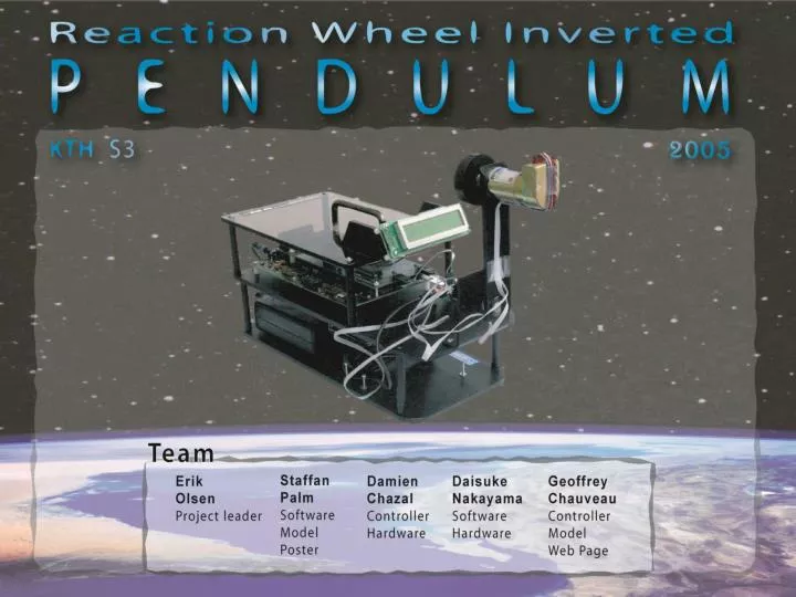
The Plant • Pendulum • Reaction Wheel • Motor • Encoders • TI Digital Signal Processor • PWM Motor Driver
Reaction Wheel • Wheel acceleration by torque from motor • Torque on motor from wheel inertia • Torque is transferred to the whole pendulum
Applications of Reaction Wheels • Satellite adjustment • Motorcycle mid-jumpcorrection
Model Derivation • Three states • Model derived by laws of physics and measurements
Hybrid Automaton • Two discrete states • Swinging State • Balancing State
Swing Up Controller • Bang-bang energy control • Energy of pendulum • Wtotal = Wpotential + Wkinetic • Reference value is the potential energy at the upright position • The pendulum will reach the catch angle with the right amount of speed
Continuous time Plant h Continuous time Controller Discretized Plant h Discrete Controller Two Approaches of Controller Design • Design in Continuous Time • Design in Discrete Time
Process Controller State Feedback State observer Design in Continuous Time • Design of a State Feedback Controller • Investigate PD controller:
Analysis of the Root Locus • Root locus : closed-loop pole trajectories as a function of
A Stable Closed-loop System necessity of a feedback on
hold sample State Feedback State observer Sampling of the controller • Discrete transformation of the derivatives in using backward difference • Filtering of the velocities and First order low pass filter
Higher overshoot in reality (Nonlinearities such as dry friction) High rising time (>1.5s) Open loop plant has 3 poles : 8.82, -8,72, 7.64 2 turns around -1 stable closed loop Performance of the PD-controller
LQ-controller • How to choose for optimal results? Computed from the continuous plant state matrices With , and gives optimal solution
Performance of the LQ-controller • No overshoot. • Phase margin 60 degrees
Performance of the LQ-controller Demo of the continuous LQ…
Discrete Plant State observer Design in Discrete Time • Plant is sampled with a zero-order hold approximation. • LQ controller derived with the discrete plant state matrices : • with • Gives optimum solution for any sampling period h :
Performance of the Discrete LQ-controller Demo of continuous and discrete LQ…
Deadbeat Control • Use a state feedback • The strategy: drive the state into the origin in at most 3 steps • Possible if • Cayley-Hamilton theorem states that if the desired closed loop poles are put at the origin,
Performance of the Deadbeat Controller Demo of the Deadbeat Controller…
Embedded behaviour • CPU time 2% no pb with deadlines not met • Sampling frequency VS control performance • Maximum sampling period h=150 ms according to rising time of motor
Conclusion • Energy controller for swinging up the pendulum gives good results. • Continuous LQ works fine with high sampling frequency • For lower sampling frequencies, discrete design of controller needed. • Deadbeat controller does not work because of voltage limitations