Download
1 / 7
70 likes | 82 Views
RC CIRCUITS: Charging. Time constant = τ = RC. What is the unit for RC ?. RC Circuits: Discharging. Time constant = τ = RC. Camera Flash.

E N D
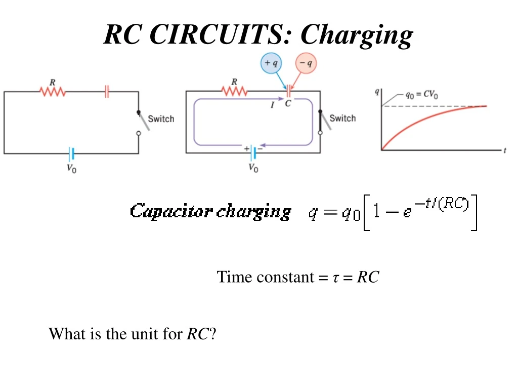
RC CIRCUITS: Charging Time constant = τ = RC What is the unit for RC?
RC Circuits: Discharging Time constant = τ = RC
Camera Flash The lamp in this circuit ordinarily has a very high resistance, so that the battery charges the capacitor as if the lamp were not there. When the voltage reaches a threshold value, a current flows through the lamp that dramatically reduces its resistance, and the capacitor discharges through the lamp as if the battery and charging resistor were not there. Once discharged, the process starts again, with the flash period determined by the time constant, . A graph of voltage versus time for this circuit.
Problem 65, Chap 21 This stop-motion photograph of a rufous hummingbird (Selasphorusrufus) feeding on a flower was obtained with an extremely brief and intense flash of light powered by the discharge of a capacitor through a gas. (credit: Dean E. Biggins, U.S. Fish and Wildlife Service) P65 Chap21: The duration of a photographic flash is related to an RC time constant, which is 0.100 μs for a certain camera. (a) If the resistance of the flash lamp is 0.0400 Ω during discharge, what is the size of the capacitor supplying its energy? (b) What is the time constant for charging the capacitor, if the charging resistance is 800 kΩ?
Problem 63, Chap 21 63. The timing device in an automobile’s intermittent wiper system is based on an RC time constant and utilizes a 0.500-μF capacitor and a variable resistor. Over what range must R be made to vary to achieve time constants from 2.00 to 15.0 s?
The physics of heart pacemakers • Heart pacemakers, for instance, incorporate RC circuits to control the timing of voltage pulses that are delivered to a malfunctioning heart to regulate its beating cycle. • RC circuits are used for timing purposes in the artificial pacemaker, used to control heart rate. The heart rate is normally controlled by electrical signals generated by the sino-atrial (SA) node, which is on the wall of the right atrium chamber. This causes the muscles to contract and pump blood. Sometimes the heart rhythm is abnormal and the heartbeat is too high or too low. • The artificial pacemaker is inserted near the heart to provide electrical signals to the heart when needed with the appropriate time constant. Pacemakers have sensors that detect body motion and breathing to increase the heart rate during exercise to meet the body’s increased needs for blood and oxygen.
Problem-69 Chap 21 69. A heart defibrillator being used on a patient has an RC time constant of 10.0 ms due to the resistance of the patient and the capacitance of the defibrillator. (a) If the defibrillator has an 8.00-μF capacitance, what is the resistance of the path through the patient? (b) If the initial voltage is 12.0 kV, how long does it take to decline to 600 V ? {Such brief times are useful in heart defibrillation, because the brief but intense current causes a brief but effective contraction of the heart}