Download
1 / 38
390 likes | 583 Views
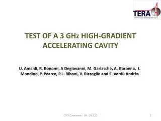
High-Gradient Test of a 3 GHz Single-Cell Cavity. 4th Annual X-band Structure Collaboration Meeting Silvia Verdú -Andrés (TERA, IFIC) U. Amaldi, M. Garlasché (TERA), R. Bonomi (TERA, Politecnico di Torino), A. Degiovanni, A. Garonna (TERA, EPFL),

E N D
High-Gradient Test of a 3 GHz Single-Cell Cavity 4th Annual X-band Structure Collaboration Meeting Silvia Verdú-Andrés (TERA, IFIC) U. Amaldi, M. Garlasché (TERA), R. Bonomi (TERA, Politecnicodi Torino), A. Degiovanni, A. Garonna (TERA, EPFL), R. Wegner (TERA, CERN), C. Mellace (A.D.A.M.) 03.05.2010
27 cm Tumour target Charged hadron beam that loses energy in matter proton tail light ion (carbon) httt://global.mitsubishielectric.com/bu/particlebeam/index_b.html Hadrontherapy: the basics 200 MeV - 1 nA protons 4800 MeV – 0.1 nA carbon ions (radioresistanttumours) Depth-dose distribution Courtesy of PSI Silvia Verdú-Andrés
Treatingmovingorgansrequires... • Fast Active Energy Modulation (a couple of ms) Fast 3D correction of beam spot position in depth Lateral scanning with magnets: 2 ms/step Single ‘spot’ pencil beam • Fast Cycling machine (high repetition rate ~ 200-300 Hz) Tumour MULTIPAINTING Depth scanning: ACTIVE ENERGY MODULATION 3D conformal treatment Silvia Verdú-Andrés
TERA’sproposal:cyclotron + high-freq. linac = cyclinac 120 MeV/u CELL COUPLED LINAC 400 MeV/u • Cell Coupled Linac • Standing-wave structure • RF frequency: 5.7 GHz Cell Coupled Linac RF frequency: 5.7 GHz 18 accelerating modules - Length of each module ~ 1.3 m High gradient : 40 MV/m (TERA+CLIC collaboration) Silvia Verdú-Andrés CABOTO (CArbon BOoster for Therapy in Oncology)
Higheraccelerating gradients • Smallercomplex! TERA’s proposal:cyclotron + high-freq. linac = cyclinac 120 MeV/u CELL COUPLED LINAC Cyclinac: E0 ~ 40 MV/m EMax ~ 200 MV/m BDR ~ 10-6 bpp/m in 30 m 400 MeV/u CABOTO = CArbon BOoster for Therapy in Oncology Cell Coupled Linac RF frequency: 5.7 GHz 18 accelerating modules - Length of each module ~ 1.3 m High gradient : 40 MV/m (TERA+CLIC collaboration) Silvia Verdú-Andrés
3 GHz high-gradient test:motivation and objectives Silvia Verdú-Andrés 6
3 GHz high-gradient test:motivation and objectives • Operationlimit for S-band cavities Break Down Rate BDR per length • Limitgiven by: • surface fieldEs (Kilp.) or • modifiedPoyntingvectorSc+ scalinglaw (X, K-band) Silvia Verdú-Andrés
3 GHz high-gradient test:motivation and objectives • Operationlimit for S-band cavities Break Down Rate BDR per length • Limitgiven by: • surface field Es (Kilp.) or • modifiedPoyntingvectorSc+ scalinglaw (X, K-band) • Scalinglawsat S-band • [Es, Sc, pulse length, temperature, repetitionfrequency] Silvia Verdú-Andrés
3 GHz high-gradient test:motivation and objectives • Operationlimit for S-band cavities Break Down Rate BDR per length • Limitgiven by: • surface field Es (Kilp.) or • modifiedPoyntingvectorSc+ scalinglaw (X, K-band) • Scalinglawsat S-band • [Es, Sc, pulse length, temperature, repetitionfrequency] • Applyingfoundlimit to future designs • ensurereliableoperation • optimize RF structures (efficiency, length, cost) Silvia Verdú-Andrés
3 GHz high-gradient test:motivation and objectives • Operationlimit for S-band cavities Break Down Rate BDR per length • Limitgiven by: • surface field Es (Kilp.) or • modifiedPoyntingvectorSc+ scalinglaw (X, K-band) • Scalinglawsat S-band • [Es, Sc, pulse length, temperature, repetitionfrequency] • Applyingfoundlimit to future designs • ensurereliableoperation • optimize RF structures (efficiency, length, cost) single-cell test cavity Silvia Verdú-Andrés
RF & mechanical design max. E max. H max. Sc Cooling ANSYS nose Pave = 350 W Mass Flow = 2.5 L/min Df/DT= -1.1 MHz / 20K β= 0.38 (Ekin=70 MeV) f0= 3000 MHz Q0= 9000 Emax/E0 = 6.5 Silvia Verdú-Andrés
Production • OFE copper • 0.02 mm tolerance • 0.4 mm roughness Accelerating cell @ 3 GHz (two unsymmetrical half cells) RF coupling system (waveguide, short circuit) Cooling system (two plates, in-out pipes) Connection to data acquisition (through CF flanges) Silvia Verdú-Andrés
Production • Machining at Veca (Modena, Italy) • Cleaning at CERN (Geneva, Switzerland) • (vacuum) Brazing at Bodycote (Annecy, France) Done in less than one month! Silvia Verdú-Andrés
Low power test RF input Short Circuit Test Cavity f0= 3000.2 MHz Q0= 8650 (96% Q0,sim) b = 0.92, G=-27 dB Silvia Verdú-Andrés
First high-power test: objectives • Debugging test set-up and cavity • First check of cavity behaviour under high-power • Finding improvements for precision test to evaluate scaling laws [BDR(Es, Tp, frep)] • Only 1-2 weeks foreseen for test Purpose of first test: 1. First check of RF behaviour of test cavity 2.Debugging set-up and test of cavity 3. Finding improvements for precision test(machining, instrumentation, data acquisition) to evaluate scaling laws [BDR(Es, Tp, frep)] Silvia Verdú-Andrés
High power test: set-up @ CTF3 • Faraday Cup • Peak Power Analyser • Temperature sensors • no Data Acquisition System • no control system for stabilising frequency & amplitude • no RF Pickup Silvia Verdú-Andrés
High power test: measurements Peak Power Meter PFW PREF Tpulse= 5 ms • no RF Pickup relying on power measurements frep= 50 Hz • Pcav = PFW-PRF • At resonance: adjusting frequency until PREF(f) < 10% PFW(f) • Hot cavity • Eacc 17 ES= ES,calculated * 0.93
High power test: breakdown evaluation TFlat top= 3 μs Breakdown!125 pulses, 1 BD BDR= 0.8 • 10-2 Faraday Cup Breakdown! 18 Silvia Verdú-Andrés
High power test: first results Silvia Verdú-Andrés
High power test: comparison to other tests TERA Limit in copper to surface field by breakdown surface damage Gradient limitations for high frequency accelerators, S. Döbert, SLAC, Menlo Park, CA 94025, USA (2004) 20 Silvia Verdú-Andrés
High power test: comparison to other tests first results Sqrt(Sc) є[1.3-1.6] The modified Poynting vector as an RF constraint to high gradient performance 21 The square root of SC has been scaled to tpulse =200 ns and BDR=10-6 bbp/m A New Local Field Quantity Describing the High Gradient Limit of Accelerating Structures, A. Grudiev, S. Calatroni, and W. Wuensch, Phys.Rev. Accel. Beams (2009) 102001 21 Silvia Verdú-Andrés
High power test: scaling laws Treatment Session: 3 minutes @ 400 Hz Max. 1 BD per session Max.BDR: 10-6bpp/m X = 30 (otherexp.) X = 6 TERA 22 Silvia Verdú-Andrés
High power test: scaling laws Treatment Session: 3 minutes @ 400 Hz Max. 1 BD per session Not enoughstatistics for scalinglaw’sevaluation Max.BDR: 10-6bpp/m X = 30 (otherexp.) X = 6 TERA 23 Silvia Verdú-Andrés
Surface inspection aroundnoseregion [90X Optical Microscope] max. E max. H max. Sc Activity in the cavity: ~ 14000 breakdowns Silvia Verdú-Andrés
Surface inspection around nose region 50X Copper Grains (tenths of mm) Max. roughness: 0.4 mm 0.5 mm Silvia Verdú-Andrés
50X 0.5 mm Surface inspection around nose region Several craters… and a lot of activity Silvia Verdú-Andrés
Summary • Excellent Pre-Test, cavity works, even first results Silvia Verdú-Andrés
Summary • Excellent Pre-Test, cavity works, even first results • Improvements for high-precision test • cooling / water flow control • data acquisition (Pforward, Preflected, φforward, φreflected, Vfaraday cup, vacuum) • control system for stabilising frequency & amplitude Silvia Verdú-Andrés
Nextsteps: a lot to do! • High-precision high-power test of the 3GHz test cavity • Design, construction and high-power test of another single-cell cavity operating at 5.7 GHz • to evaluate scaling laws • learn more about breakdown phenomena Design has already begun; to be tested before the end of 2010! Silvia Verdú-Andrés
Thanks to… All the Cyclinac team for their support And all of you for the attention! The research leading to these results has received funding from the Seventh Framework Programme [FP7/2007-2013] under grant agreement n° 215840-2. TERA -Cyclinac team • CLIC RF and Breakdown Group • CTF3 Group • CERN General Services • VECA, Bodycote, ADAM • Vodafone Silvia Verdú-Andrés
BACK-UP SLIDES Silvia Verdú-Andrés
RF & mechanical design • Requirements • Average power to cool (350 W) • Nº of parallel circuit (2) • Turbulent flow • Avoid erosion/corrosion • Reference temp. for coolant properties (37ºC) • High heat transfer coefficient • Choices • dTin-out = 1ºC • Deq = 5.5 mm • Re = 13900 • v = 1.77 m/s • h = 10020 W/m2/K • Mass flow 2.5 l/min • Δf0 / ΔTRF = - 1.1 MHz / 20 K Silvia Verdú-Andrés
Halfcell design 33 Silvia Verdú-Andrés
Cooling design OFE Copper / 316 L Two pipes coated and brazed to cooling plate Qwater < 2.5 l/min Silvia Verdú-Andrés
Waveguide design Design evolution: Standard WR-284 (OFE copper) with two LIL flanges for connection to RF source and short Silvia Verdú-Andrés
ES= 150 MV/m SC= 0.46 MW/mm2 ES/E0= 6.5 P = 128 kW Cavity Performance SF EK= 47 MV/m Measure Measure Measure Old values MAX Silvia Verdú-Andrés
Surface inspection aroundnoseregion [90X Optical Microscope] Activity in the cavity: ~ 14000 breakdowns Silvia Verdú-Andrés