Download
1 / 22
250 likes | 951 Views
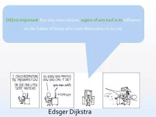
The Structure of “THE” – Multiprogramming System Edsger W. Dijkstra. Presented by: Slobodan Stipic Martin Dimitrov. Inspiring Quote.

E N D
The Structure of “THE” – Multiprogramming SystemEdsger W. Dijkstra Presented by: Slobodan Stipic Martin Dimitrov
Inspiring Quote Be aware of the fact that experience does by no means automatically lead to wisdom and understanding; in other words, make conscious effort to learn as much as possible from your previous experiences.
Overview • Introduction • EL X8 - the tool • New operating system ideas • Storage allocation (paging, virtual memory) • Processor allocation and synchronization (semaphores) • Layered architecture (six layers) • Proof of correctness of the system • Summary
Introduction • Developed in 1968 by Dijkstra • Goal: • Reduction in turnaround time for programs of short duration • Economic use of peripheral devices • Automatic control of backing store and CPU • Flexibility of general purpose computer needed, not the capacity or power.
The Tool • EL X8 • Core memory cycle time 2.5 μsec, 27 bits, 32K • Drum of 512K words, 1024 words per track, revolution time 40 msec • An indirect addressing (suited for stack implementation) • A sound control of interrupts and peripherals • Peripherals: 3 paper tape readers, 3 paper tape punchers, 2 teleprinters, 1 plotter, 1 line printer • Absence of number of unnecessary features
New Operating System Ideas • Storage allocation (paging, virtual memory) • Processor allocation and synchronization (semaphores) • Layered architecture (six layers) • Proof of correctness of the system
Storage allocation • Large uniform virtual store • Segments - logical unit • Main store and drum store • Pages - physical unit • Main page table and drum page table
Segment replacement • Number of segments limited only by the size of the drum • LRU • Implemented entirely by software
Physical memory • Drum store • 512 tracks (1024 words/track) • 2 pages • 2 states per page • Main store • 48K words (about 70 pages for user programs) • 4 states per page: free, in use, incoming, victim
Main store page states • Free - forms a stack • In use - if altered then needs to be written to the drum, otherwise discarded. • Incoming - in transition from “free” to in “use” • Victim – only one at any time
Processor allocation and synchronization • System as a society of cooperating processes • Semaphores-explicit mutual synchronization • Private semaphore • Range: 1,0,-1 • Mutual exclusion semaphores • Range: 1 to n-1
Private Semaphores Process 1 P(mutex) If resource available then V(private semaphore) V(mutex) P(private semaphore) ********************************************* Process 2 P(mutex) Release resource V(private semaphore) V(mutex)
Layered Architecture • Level 0 - processor allocation and synchronization • Level 1 – segment controller • Level 2 – message interpreter • Level 3 – I/O services • Level 4 – user programs • Level 5 - operator
Level 0 – Processor allocation and synchronization • Processor allocation and synchronization • Timer interrupt • Priority rule • Abstracts number of shared processors
Level 1 – Segment Controller • Drum storage management • Presents storage interface in terms of segments
Level 2 – Message interpreter • Handles keyboard and output printer • Communication between operator and higher level processes • Justification for the placement of message interpreter in the Level 2 of the hierarchy
Level 3 – I/O Service • Buffered input/output • Processes associated with the peripherals are a level above the message interpreter • Mutual synchronization for resources provided to the higher levels
Level 4 & Level 5 • Level 4 consists of user programs • Level 5 – user programs are invoked by the operator
Proving the harmonious cooperation • Society of cooperating processes • Explicitly synchronized using semaphores • Eliminates time dependent phenomena “So effectively structured that at each stage of the testing procedure the number of relevant test cases will be so small that he can try them all.”
Proving the harmonious cooperation • Notion of “homing position” and “unstable situation” • Proof outline: • Process performing a task can generate only a finite number of tasks • System cannot be at rest if there are still pending tasks • All processes will eventually be in homing position (no deadlock)
Summary • Storage allocation (paging, virtual memory) • Processor allocation and synchronization (semaphores) • Layered architecture (six layers) • Proof of correctness of the system “The resulting system is guaranteed to be flawless.” - Dijkstra
References • E. W. Dijkstra, “The structure of the THE – multiprogramming system, “Communications of the ACM, vol II, number 5, pp. 341-346, May 1968 • R. M. McKeag & R. Wilson, “Studies in Operating System,” Academic Press, pp. 145-184,1976