Download
1 / 29
290 likes | 300 Views
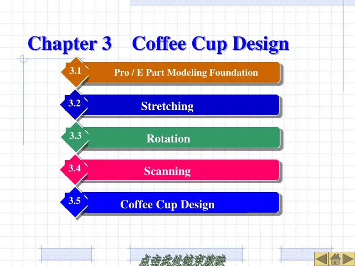
3.2. 3.1. 3.3. 3.4. 3.5. Pro / E Part Modeling Foundation. Stretching. Rotation. Scanning. Coffee C up D esign. Chapter 3 Coffee Cup Design. 3.1 Pro / E Part Modeling Foundation.

E N D
3.2 3.1 3.3 3.4 3.5 Pro / E Part Modeling Foundation Stretching Rotation Scanning Coffee Cup Design Chapter 3Coffee Cup Design
3.1 Pro / E Part Modeling Foundation • In Pro / E system, features are the most basic unit of design and operation, while basic features are the basis and carrier of other features in the part model. • When modeling a part, it is necessary to conduct an in-depth feature analysis of the model, find out the part model is composed of what kind of features , define the shape of each feature and its relative relationship, and then model according to the primary and secondary features in a certain order.
3.1.1 Features and Classification • 1. Solid features, surface features and datum features • 2. Basic features and engineering features • Basic feature: the first entity feature created during modeling; Engineering features: other features established later than basic features. Engineering features include sketch and placement features. • 3. Sketch - type features and placement - type features • Sketched features: features that can only be generated by drawing two-dimensional sections during feature creation; Placement Features: Some parameterized features defined inside the system. Solid features Cut 1 Hole1 Cut 2 Solid features Hole 2 Reference features Rotor body Figure 3-2 Classification of basic features and engineering features Figure 3-1 Types of Features
3.1.2 Definition of sketch plane and reference plane When sketching a section, you must define a sketch plane and a reference plane, and the reference plane must be perpendicular to the sketch plane. Sketch plane refers to the two-dimensional plane used to draw the section. The reference plane refers to the two-dimensional plane used to determine the placement orientation of the sketch plane, that is, to assist positioning of the sketch plane. Sketch When entering sketch mode, the system will automatically adjust the viewing angle to a plain plane drawing state, that is, place the sketch plane parallel to the screen along the specified sketch view direction. Agreement on Normal Direction of Reference Plane: The positive direction of the reference plane is indicated by the brown side of the plane, and the gray side represents its negative direction. Sketch view direction Sketch plane Reference plane Figure 3-3 Sketching dialog box Figure 3-4 Reference plane selection (b) Reference surface plane downwards (d) Reference surface plane to left (a) Reference surface plane upwards (c) Reference surface plane to right Figure 3-5 The Relationship between sketch plane placement and reference plane orientation
3.1.3 Setting of Template Model English and metric design environments, namely in lbs _ part _ solid ( English part ) and mmns _ part _ solid ( metric part ), are two built-in template models. New folder New Figure 3-6 Create New dialog box Figure 3-7 Create New folder dialog box
3.1.4 Setting of Model Units Two methods of setting model units: use the system configuration file config. pro to preset, that is, select tools - > options to set the option values of pro _ unit _ length and pro _ unit _ mass; Select [Edit] → [Setup] → [Units] to temporarily set up the unit system of the model. (1) Convert Dimensions: Perform unit changes at the same size, i.e. the part model size (volume) remains unchanged and only the dimension values are scaled. (2) Interpreting Dimensions: Perform unit changes according to the same dimensions, that is, keep the dimension value of the part model unchanged while the model size changes. Unit manager Menu manager Change model unit Part setting Model Parameter Unit Figure 3-8 Part setting menu Figure 3-9 Unit manager dialog box Figure 3-10 Unit system conversion
3.1.5 Setting of Model Materials Select [Edit] → [Set Up] → [Material] command. Material Figure 3-11 Material dialog box
3.1.6 The General Principle of Basic Feature Generation Four basic feature creation methods: Extrude: The feature section grows or cuts out along its vertical direction, with equal section properties. Revolve: The feature section revolves around a center line and has an axisymmetric property. Sweep: A section is swept along a trajectory line and has equal section properties in the orthogonal direction of the trajectory. Blend: A series of sections ( more than two ) are connected in sequence. Feature section Feature section Figure 3-12 Extrusion Figure 3-13 Revolve Cross-section 1 Trajectory Cross-section 2 Cross-section Cross-section Figure 3-14 Scan Figure 3-15 Mixture
3.2 Stretching • Stretching feature refers to the volume of surface, solid body or thin body that the feature section grows vertically along the normal direction of its extruding plane. It is suitable for constructing equal section features. Feature section Figure 3-12 Extrusion
3.2.1 General Flow of StretchOperation • 1. Set the stretch feature type • ( 1 ) Click the extruding button or select [Insert] → [Extrude]; • ( 2 ) Set solid or curved surface extruding in the stretch control panel; • 2. Draw the characteristic section • ( 1 ) Click the Placement button of the dashboard to open the placement slide - up panel. • ( 2 ) Specify the sketch plane, reference plane and its direction in the Sketch dialog box; • ( 3 ) Enter sketch mode and define appropriate sketch reference; • ( 4 ) Draw or retrieve the feature section, and then finish. • 3. Set the parameters of the stretching feature • ( 1 ) Set the stretching depth in the extruding control panel; • ( 2 ) Set the thickness and direction of the material removal area or thin body; • ( 3 ) Perform feature preview or feature generation, and change the view angle of the model for viewing.
3.2.2 Stretch Control Panel 1. Stretch the dialog bar of the dashboard 2. Stretch the slide - up panel of the dashboard: Placement/ Options/Properties Reverse feature creation direction Shell Cancel Pause Solid Shell thickness definition box Deep define box Create feature Shell thickness direction Deep option Surface Preview Material removal Figure 3-23 Stretch control panel Deep Figure 3-24 ‘Place’ panel Figure 3-25 ‘Option’ panel Figure 3-26 ‘Property’ panel
3.2.3 Stretch Feature Type Stretch feature types and their corresponding control panel uses Form 3-1 Features of model Feature types Use of Control panel Extrusion Shell extrusion Solid removal Shell removal Surface extrusion Surface trim
3.2.4 Depth Definition of Stretch Features The depth definition form and function of stretch feature and its application description Form 3-2 Functions and application descriptions Definition of depth forms Stretch the section from the sketched plane at a specified depth value (negative value reverses direction) Stretch the section symmetrically to both sides of the sketch plane by half of the specified depth value Automatically stretch the section to the next surface in the stretching direction (except for the reference plane) Select Property Stretch the section in the stretch direction to make all surfaces are intersect (throughout the part) Figure 3-27 Depth Definition of Stretch Features Stretch the section to the selected surface or reference plane in the stretch direction Along stretch direction to stretch the section up to the selected object, it’s similar to thru until Depth 1st side 2nd side Option Figure 3-29 Define different depths on both sides Figure 3-28 Depth definition of stretch features
3.2.5 Example Exercises • Example 3 - 1 Referring to Figure 3 - 30, create a bearing seat part. • Step 1: Establish the base features • Step 2: Establish pillar features • Step 3: Establish concave hole features • Step 4: Establish that characteristics of the stiffeners Figure 3-30 Bearing pedestal
3.2.5 Example Exercises Figure 3-38 The result of model effect Figure 3-35 Sketch section Figure 3-32 Characteristic section of basic body Figure 3-37 Sketch the section of the rotation feature Figure 3-43 Sketch the section of the rib plate Figure 3-44 The result of model effect Figure 3-39 Cross-section of a circular sketch Figure 3-41 Sketch cross-section
3.3 Rotation Rotational feature refers to a curved surface, solid body or thin body swept out by rotating a characteristic cross section around a central axis at a specific angle, which has an axisymmetric characteristic (i.e., the cross sections on both sides obtained are in a symmetrical state when cutting along the central axis). Feature cross-section Figure 3-13 Revolve
3.3.1General flow of Rotating Operation 1. Set the rotation feature type ( 1 ) Click the rotate button or [Insert] → [Rotate]. ( 2 ) Set as solid or surface rotation in the rotation dashboard. 2. Draw the characteristic section ( 1 ) Slide the panel up in the open position to sketch the section. ( 2 ) Define the sketch plane, reference plane and its direction in the sketch dialog box. ( 3 ) Enter the sketch mode and specify the appropriate sketch reference. ( 4 ) Draw or transfer the section as the current characteristic section, and then finish. 3. Set the parameters of the rotation feature ( 1 ) Set the rotation angle in the rotation feature control panel. ( 2 ) Set cutting feature's material removal area or thickness and direction of the thin body. ( 3 ) Perform feature preview or feature generation and change the viewing angle to see the model effect.
Define thickness of shell Angle define box Material removal • 3.3.2 RotationControl Panel Property Position Option Change revolve direction Axis collector Solid Surface Angle option Shell Change shell thickness direction Figure 3-50 Revolve control panel Angle Sketch Figure 3-51 ‘Position’ panel Figure 3-52 ‘Option’ panel
Requirements for sketching sections when creating rotating features: ( 1 ) A centerline must be established in the section as the axis of rotation. ( 2 ) If the feature is a solid body, its cross section must be closed. ( 3 ) All section elements must be located on the same side of the axis of rotation. ( 4 ) If there are two or more centrelines in the section, the system defaults the first centreline as the axis of rotation. Therefore, when sketching a section of a rotating feature, it is necessary to develop the habit of drawing the center line (feature rotation axis) first. • 3.3.3 Section of Rotating Feature
The system provides three ways to define the rotation angle: • 3.3.4 The Angular Definition of the Rotation Feature Figure 3-53 Angle define of revolve feature Angle define of revolve features, functions and descriptions Form 3-3 Type of angle defines Functions and descriptions According the designated value to crate cross-section from sketch plane to side According the half of designated value to crate symmetric revolve feature from sketch plane Revolve the feature up to the selected object, but the ending surface must include rotation axis Functions and descriptions
3.3.5 Example Exercises Example 3 - 2 Establishe a pulley part as shown in fig. 3 - 54. Step 1: Establish the basic body characteristics of the pulley Step 2:Establish a grooved feature Step 3:Establish the characteristics of the shaft hole and the weight reduction hole Figure 3-54 Pulley part
3.3.5 Example Exercises Figure 3-55 Cross-section of revolve part Figure 3-59 Grooved array effects Figure 3-60 Sketch cross section of shaft hole Figure 3-57 Sketch a grooved feature section Figure 3-62 3D model of pulley Figure 3-61 Sketch cross section of weight lightning hole
3.4 Scanning Scanning refers to the movement of a two-dimensional section along a plane or space trajectory to form a curved surface or solid feature. When you create a scan feature, there are seven types: Stretch, Sheet Stretch, Cut, Sheet Cut, Surface, Surface Trim, and Thin Surface Trim. The scanning feature is composed of two elements: trajectory and cross section. The cross section always does not change during scanning and is perpendicular to the selected trajectory. Scan Figure 3-63 Type of scan feature created
3.4.1 The attributes of the scan feature ( 1 ) The trajectory is closed and the section is closed or open. [Add Inn FCS (Increase Internal Factors)]: Automatically add internal top and bottom surfaces to form internal entities, limited to open sections; [ no inn FCS ( without internal factors ) ]: no internal surface is added, only limited to closed section. ( 2 ) The trajectory is open (and one end is connected to the existing entity) and the section must be closed. [Merge Ends]: Automatically extend scan features and merge scan endpoints into neighboring entities; [Free Ends] Scanning endpoints do not connect with neighboring entities. Figure 3-64 Attribute settings for closed trajectory Figure 3-67 Add internal factors Figure 3-64 No internal factors (a) Merge ends (b) Free ends Figure 3-67 Attribute settings for open trajectory Figure 3-68 Different Effects of Two Attribute Settings Figure 3-66 No internal factors
3.4.2 The general flow of scanning operations ( taking entity characteristics as an example ) 1. Specify the type of scan feature creation Select [Insert] → [Sweep] → [Protrusion] 2. Define the scan trajectory ( 1 ) Select Sketch Traj to sketch the scan trajectory, or Select Traj to select an existing curve or edge chain as the scan trajectory. ( 2 ) Define the sketch plane, reference plane and its direction. ( 3 ) Enter sketch mode to draw the required trajectory. 3. Define attributes and sections of scan features ( 1 ) Open tracks and connect with existing feature entities: Merge Ends or Free Ends. ( 2 ) Closed trajectory: add internal factor ( Add Inn FCS ) or no internal factor (No Inn Fcs ). 4. Define the section of the scan feature ( 1 ) Automatically enter the sketch mode and draw the section of the scanning feature. ( 2 ) Specify the removal side of the scanned notch material. ( 3 ) Perform the creation of scanning features.
3.4.3 How to Create Scan Track Two methods of definition: sketch traj and select traj ( 1 ) [ Sketch Traj ]: Sketch plane and reference plane need to be set in order to draw the outline of the trajectory, and the trajectory is limited to two-dimensional curves; ( 2 ) [ Select Traj ]: Select an existing curve or solid edge chain as the trajectory, which can be a three-dimensional curve. Using the existing curve as the scanning trajectory, the system will ask the direction of the horizontal reference plane, that is, the upward direction of the plane where the scanning section is located ( Y - axis positive direction ). Figure 3-72 Select track and scan section orientation setting
3.4.4 Example Exercises Example 3 - 3 Build the parts of the kettle as shown in Figure 3 - 73. Step 1Build the basic features of the rotating body Step 2Build a support plate at the bottom of the rotating body Step 3 Build the outer thin wall of the kettle handle Step 4 Build the inner thin wall of the kettle handle Step 5 Build a connecting plate in the middle of the handle (b) Right View (a) Front View Figure 3-90 Kettle 3D model Figure 3-73 Kettle
3.4.4 Example Exercises Center Axis Center Axis Align with the endpoint of the outer line Sketch ref. Figure 3-76 Sketch of section of the revolver foundation feature Figure 3-79 Cross - section of brace features Figure 3-82 Scan trajectory of sketch Closed cross-section Sketch reference line Figure 3-87 Scan feature of cross-section sketch Figure 3-89 Cross-section shape Figure 3-86 Scan of trajectory sketch Figure 3-90 3D model of kettle
Exercise Figure 3-126 Model practice 1 Figure 3-127 Model practice 2