Download
1 / 10
100 likes | 193 Views
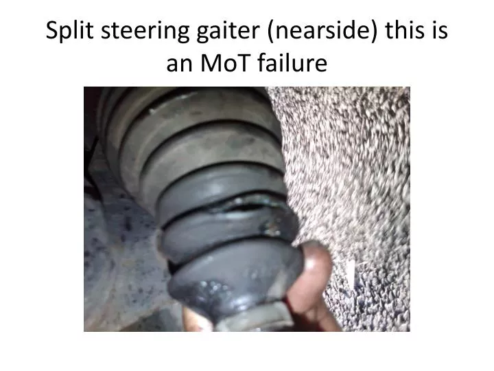
Split steering gaiter (nearside) this is an MoT failure. SAFETY FIRST!!!!!!!. Place car on level ground Select 1 st gear or put selector in Park. Chock the rear wheels

E N D
SAFETY FIRST!!!!!!! Place car on level ground Select 1st gear or put selector in Park. Chock the rear wheels Release the wheel nuts ¼ turn – until they turn freely - Do not remove at this stage (The wheel nuts will be tight you need the friction of the tyre against the road surface to release them Jack up the car and support the suspension with proprietary supports such as axle stands – do not use bricks or rely on the jack – a 3200 weighs over 1500kg Remove the wheel nuts and remove the road wheel – the wheel makes a handy seat to save those knees!
Use a steel rule against the locknut to mark the steering arm with a sharp scribeThis is ESENTIAL to ensure steering geometry can be reset – you will need to scratch the steel as greasy fingers will soon remove any marks in the road dirt leaving you with no idea where the steering geometry was – make a note of the value you use Lock nut Mark the steering arm with a SHARP metal scribe Avoid the castellated area – its for a spanner
Spray the lock nut with WD40 – leave for a few minutes to penetrate use a 22mm spanner to undo the lock nut, ¼ turn, a 13mm spanner is needed to stop the steering arm rotating on its joint, this can be braced against the lower wishbone as shown so you wont need 2 hands Front anti roll bar 13mm spanner on castellated part of steering arm Lower wishbone Track rod or steering arm end 22mm spanner to release the lock nut – note turn clock wise as you face the side of the vehicle – the nut needs to move AWAY from the track rod end
1 Release the lock nut on top of the ball joint with a socket and extension bar2 Undo far enough to protect the top of the joint3 Strike with a hammer sharply to release the taper 1 2 3
1 Steering arm released – unscrew the track rod end and count the number of turns – use the same number of turns when replacing to keep the tracking in the right ballpark (it will need to be checked on a machine for exact settings)2 Release the plastic clips with a pair of pliers – if they break replace with plastic cable ties - remember to make sure they don’t foul any thing so cut off the excess. The inner clips are metal and normally break when removed – new ones are supplied in the kit
Slide off the gaiter and clean off all the excess grease and dirt – its grey brown because the split in the gaiter has let water in Ball and socket joint Check for wear and excessive movement This slides in and out check for wear
1 New parts (top) old removed parts (bottom) – note slight difference in the track rod end2 Remove the tapered collet with a ball joint splitter – this will be very tight a puller may do the job3 New track rod end with reused collet and washer – note a new nut is supplied but not a washer 1 3 Collet 2
1 Slide the new gaiter over the steering arm don’t forget the clip if using the metal crimp clips shown, and ensure everything moves freely – some more grease maybe required on the rack and ball joint, especially if the gaiter was split. The gaiter fits over a raised flange ensure this does not come off 2 Crimp the clip when you are sure its in the right position – a plastic cable tie will do the trick if this clip breaks
1 Re fitting is the reverse of the removal don’t forget to count the turns and check the measurements marked on the arm with a steel ruler Lock nut make sure this is tight A trolley jack is used to force the taper into the aluminium carrier – the thread to the ball joint is an interference fit its too tight to do up by hand so the pin will rotate if not pushed home – you will never tighten the nut!