Download
1 / 3
30 likes | 127 Views
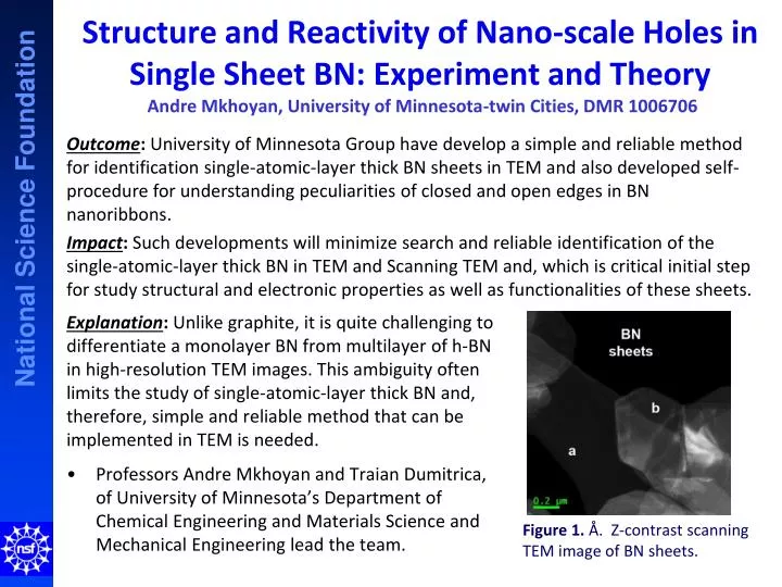
Structure and Reactivity of Nano -scale Holes in Single Sheet BN: Experiment and Theory Andre Mkhoyan , University of Minnesota-twin Cities, DMR 1006706.

E N D
Structure and Reactivity of Nano-scale Holes in Single Sheet BN: Experiment and TheoryAndre Mkhoyan, University of Minnesota-twin Cities, DMR 1006706 • Professors Andre Mkhoyan and TraianDumitrica, of University of Minnesota’s Department of Chemical Engineering and Materials Science and Mechanical Engineering lead the team. • Outcome: University of Minnesota Group have develop a simple and reliable method for identification single-atomic-layer thick BN sheets in TEM and also developed self-procedure for understanding peculiarities of closed and open edges in BN nanoribbons. • Impact: Such developments willminimize search and reliable identification of the single-atomic-layer thick BN in TEM and Scanning TEM and, which is critical initial step for study structural and electronic properties as well as functionalities of these sheets. Explanation: Unlike graphite, it is quite challenging to differentiate a monolayer BN from multilayer of h-BN in high-resolution TEM images. This ambiguity often limits the study of single-atomic-layer thick BN and, therefore, simple and reliable method that can be implemented in TEM is needed. Figure 1. Å. Z-contrast scanning TEM image of BN sheets.
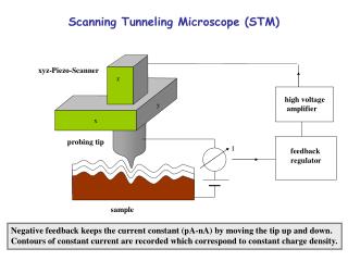
Structure and Reactivity of Nano-scale Holes in Single Sheet BN: Experiment and Theory Andre Mkhoyan, University of Minnesota-Twin Cities, DMR 1006706 • To have a reliable method of identification of single-layer BN in the transmission electron microscope (TEM), the changes in annular-dark-field scanning TEM (ADF-STEM) images, conventional bright-field TEM (BF-CTEM) images, and selected-area electron diffraction (SAED) patterns as atomically thin hexagonal boron nitride (h-BN) samples are tilted off of the [0001] zone axis were studied. It was discovered that for monolayer BN the contrast of ADF-STEM images and SAED patterns does not change with tilt, while the contrast of BF-CTEM images does change. The observations indicate that tilt series analysis of ADF-STEM images or SAED patterns permits simple and clear identification of h-BN monolayers from raw TEM data. Figure 2. Series of simulated ADF-STEM images of h-BN for an aberration-corrected 100 keV STEM with tilt. For a one-layer-thick region, tilt only serves to produce a distorted projection of the honeycomb-structured layer; for multiple-layer regions, tilting introduces distinctive complex distortions to the images, visible as streaking perpendicular to the tilt-axis. Scale bar length 2 Å.
Wedge-cut TEM as a Educational Tool Andre Mkhoyan, University of Minnesota-Twin Cities, DMR 1006706 • In collaboration with the Characterization Facility of the University of Minnesota, a decommissioned TEM is in its final stage of transformation into demonstration units. The microscopes is mechanically wedge-cut in such a way that all the internal parts are readily visible (see Figure). The microscopes will be excellent teaching tools to illustrate all critical internal elements such as electron guns, lenses for electron optics, apertures, stages, spectrometers, detectors, etc. and to understand their role in microscope operation. Relevant visuals will also be developed. The microscopes and visuals will be displayed in a main floor of the Characterization Facility. Due to the large number of people visiting the facility, including a number of students and teachers from local high schools, we expect that this initiative will have a tremendous impact. Figure 3. Wedge-cut JEOL 1210 TEM at the University of Minnesota Characterization Facility in its final stage of as a demonstration unit for educational purposes for students and visitors (courtesy of A. Mkhoyan)