Download
1 / 38
380 likes | 503 Views
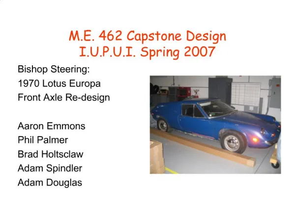
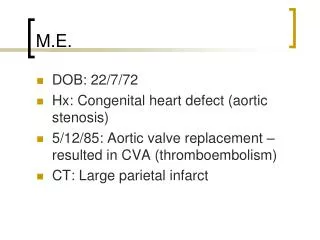
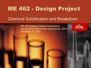
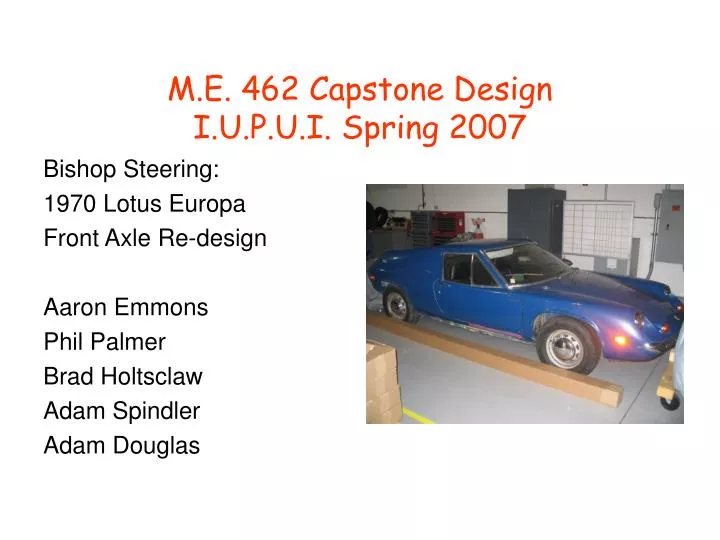
M.E. 462 Capstone Design I.U.P.U.I. Spring 2007. Bishop Steering: 1970 Lotus Europa Front Axle Re-design Aaron Emmons Phil Palmer Brad Holtsclaw Adam Spindler Adam Douglas. Agenda. Introduction Design Specifications Development Benchmarks Concept Development Evaluation Conclusions

E N D
M.E. 462 Capstone DesignI.U.P.U.I. Spring 2007 Bishop Steering: 1970 Lotus Europa Front Axle Re-design Aaron Emmons Phil Palmer Brad Holtsclaw Adam Spindler Adam Douglas
Agenda • Introduction • Design • Specifications Development • Benchmarks • Concept Development • Evaluation • Conclusions • Closing Comments • Questions
IntroductionFixed Parameters Budget $3600 5” Ride Height 15” Wheels
Design Specifications Development • Customer Requirement (right) • Top Three Requirements: • Safety • Minimizing Weight • Braking from 200mph
Engineering Specifications Ground Clearance of 5 inches Weight Minimization (parts made of aluminum) New Wheel (15” Audi Wheel) Overall width (outside wheel to outside wheel) to remain the same Overall width – Distance from frame to remain the same Braking Force to compensate for 1600lbs at 200+mph (Wilwood) Rotor size increased (surface area increase for larger braking friction)
Engineering Specifications Cont. Hub size increased to compensate for 5-bolt Audi Wheel Deflection of bearings minimized Machining time increased due to no production line Factor of Safety increased (keep Jason safe at 200 mph)
Competitive Benchmarks Minimization of Weight Maintain Safe Operation Conditions Stopping Vehicle going 200 M.P.H.+
Literature / Patents • Original car, the benchmark, was the set standard.
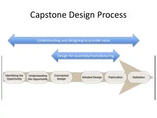
Performance Handling • Sub-Functions • Create • Order • Refine
Function-Concept Mapping • Team brainstormed methods for each function.
Concept Evaluation • Create • Overall concepts • Analyze • Using Concept Outline • Evaluate • Decision Matrix
Morphology • Two Phases • Develop concepts for functions, throughout conceptual phase. • Combining the Concepts.
Overall Concepts • Concept 1 • Tapered roller bearings • Mechanical linkage • Brake Fluid w/ piston • Rotor • Atmospheric air • Knuckle w/ ball joints • Bolts • Concept 2 • Cylindrical roller and thrust bearings • Pressurized Fluid • Mechanical linkage • Drum • Heat exchanger • Knuckle w/ pin joints • Stud w/ lug nuts
Concept Outline Brainstorming
Failure Modes • Concept 1 • Rotor • heat warping • Mechanical linkage for turning • Stress/fatigue in linkages and ball joints • Tapered bearings • Degradation due to heat and friction • Brake fluid w/ piston for stopping • Leaks/ air pockets in brake lines • Concept 2 • Drums • Heat warping the drum • Foreign debris can enter the drum easily • Heat Exchanger • Fluid lines leaking • Corrosion • Mechanical linkage system for stopping • Stress/fatigue in linkages and pin joints • Knuckle w/ pin joints • Limited number of degrees of freedom • Cylindrical roller and thrust bearings • Degradation due to heat and friction • Pressurized fluid for turning • Fluid line leaks
Critical Parameters • Following are our design parameters: • Ground Clearance of 5” • Minimum Weight • Width from wheel to wheel of 59.5” • Wheel size of 15” • Stop vehicle for speeds of 200 mph • Budget of $3600 • Width from frame to hub of 8.35” • Wheel being hub centric. • Minimum body chassis mod’s • Parts made of Aluminum (6061)
Load Distribution • Lexus V8 mounted in the rear • 60% rear 40% front • 1600 lb force on each front wheel with a factor of safety = 5
FEA: Spindle (Aluminum 6061) • 10 node tetrahedral elements • 6801 Nodes • 4068 Elements • Constrained both ends fixed • Pressure of 210 psi • Maximum Von Mises Stress is 197 psi • Yield strength of Aluminum alloy is 73 ksi
FEA: Spindle (Deflection) • Total deflection is 1.09x10⁻⁵ in. • Very minimal, and within our limits of safety.
FEA: Spindle (Shearing Stress) • Maximum shear stress occurs in the center of the spindle. • Value is 98 psi
FEA: Knuckle (Aluminum 6061) • 10 node tetrahedral elements • 6169 Nodes • 3164 Elements • Maximum Von Mises Stress was found to be 74ksi • Compared to the maximum yield stress of 39ksi • Does not meet the design requirements with a factor of safety of 5
FEA: Knuckle (Deflection) • Maxim deformation occurs at the lower control arm mount • Maximum value is 0.06 in.
FEA: Knuckle (Design Improvements) • Vertical support thicker, give the support more strength!! • 6568 Nodes • 3429 Elements • Maximum Von Mises stress is 25ksi, a percent reduction of 65% from the original. • Notice, maximum stress moved from below the control arm attachment to the top of the knuckle.
FEA: Knuckle (Maximum Shear Stress) • Maximum stress of 14ksi was found. • Percent difference of 65% from the original. • Prototype meets the engineering requirements.
FEA: Knuckle (Deflection) • Maximum deflection value of 0.02 in. was determined for the prototype.
Impact Statements • There is a definite safety risk when traveling at 200 m.p.h. • Knowing this, we have designed our parts with a safety factor of 5 to minimize risk. • Our design will have minimal impact on society or the environment
Conclusion • Aluminum is a viable material for our design • By using F.E.A. structural design of parts will withstand all applied forces with a safety factor greater than 5. • At this time, 9 out of 12 Engineering Specifications have been met.
Recommendations • Upon receiving brake components, complete dimensional analysis and collaborate with control arm group to complete assemble. • Complete the final three engineering specifications.
Acknowledgements • Dr. Hazim El-Mounayri • Bishop Steering • IUPUI Dept. of Mechanical Engineering