Download
1 / 56
560 likes | 571 Views
BASIC MATH FOR RELAY TECHNICIANS. BONNEVILLE POWER ADMINISTRATION for WSU HANDS-ON RELAY SCHOOL. INTRODUCTION - Math I.

E N D
BASIC MATH FOR RELAY TECHNICIANS BONNEVILLE POWER ADMINISTRATION for WSU HANDS-ON RELAY SCHOOL
INTRODUCTION - Math I This lecture will cover aspects of DC vs AC, why AC is so different, what is a sine wave and how it relates to phasors. We will also demonstrate how to use calculations involving right triangles to determine power factor, and to plot phasors for protective relay work.
In Service Lab • Thursday afternoon there will be an opportunity to explore the application of phasors as used in determining whether sensing devices are wired correctly, and reporting accurate information to relays. • The following information will help understand what is being done.
Mathematical Relationship of R, I, V, and P in DC • All you need to Remember is:V=IR (Ohms law), and P=VI (Joules law)…The rest just simple algebraic manipulation and substitution • [A] V=IR [1] I= V/R and [2] R = V/I • [B] P=VI [3] I= P/V and [4] V = P/I • P using [B] and [A] P = (IR)I = I2R • P using [B] and [1] P = V(V/R) = V2/R
AC vs DCDue to the nature of AC, not only do quantities such as voltage and current oscillate, but we have influences (inductance, capacitance) that can effect both a measured value and displacement in time.
AC generationas the magnet turns… This way of creating energy that builds and collapses in different directions creates a sine wave…
AC Sinusoidal Wave Magnitude Relationships VPEAK is VP-P / 2 In the power world, we refer to voltages at RMS value, not peak.
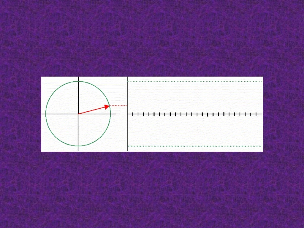
Example of two wave cycles. For relay work, this sinusoidal representation can be plotted on a coordinate system, a common language in the relay world for both engineers and craftspeople. Remember: one cycle = one 360° rotation. It can be measure from any point on the sine wave, for example, from 270° to 270°.
One cycle of the same sine wave we just viewed can be graphically represented on a Cartesian coordinate system similar to this one, depending on where in time you take your measurements. One critical point, you must draw it with reference to it’s place in time (direction) and at it’s full RMS value. 90˚ (or -270) Magnitude of 2 volts Direction of 45˚ 0, or 360˚ 180˚ Plotted with Lead angles 270˚ (or -90) RMS Value = 2 volts 45˚
Formulas for Z, I, V, P, Q, VA, PF, and RF in AC Basic relationships V=IZ, Volt-Amps=VI Z = Impedance in ohms Z=V/I* (division reverses the polarity of the angle) In addition: Power Factor, or P.F. = COS Reactive Factor, or R.F. = SIN P = Watts = VA x P.F. = VI•COS Q = Vars = VA x R.F. = VI•SIN
We used this to plot points in school. For example:X = 6, Y = 3 (purple); or perhaps X = -10, Y = -2 (green) as seen below, to define a point on the coordinate system.
As an example, values as below can be representative of True Power (watts) on the horizontal line, and Reactive Power (vars) on the vertical line. By using those two quantities, we can find the ‘hypotenuse’ or VA.
Cartesian Coordinate SystemThe summation of these quantities is proven through some basic trigonometric math. After we know the resultants magnitude and direction, we can then draw their resultant as a phasor. y, or j, is 90˚ x, or r, is 0˚, (sometimes referred to as 360 ˚) -x, or –r is 180˚ -y, or –j, is 270˚
Trigonometric Functions of a “Right Triangle” Hypotenuse Functions Inverse Functions sine() = opp/hyp arcsine(opp/hyp) = SIN-1 = cos() = adj/hyp arccosine(adj/hyp) = COS–1 = tan() = opp/adj arctangent(opp/adj) = TAN-1 = Opposite As viewed from this corner (angle of corner Adjacent It would be nice to have an easy way to remember this!
Trigonometric Functions of a “Right Triangle” Sin = O oh H heck Cos = Aanother H hour Tan = O of A Andy Another way to remember is to use the mnemonic “Oh Heck Another Hour Of Andy!” H O A What you are doing is finding the ratio, or difference in size, between the numerator (top number) and the denominator (bottom number). This ratio will be given as a percentage. That percentage can then be used to find the angle of the triangle, or . Example if H=10, O=5…… Sine = O/H = 5/10 = 0.5 (ratio), thereby SIN-1 of 0.5 = 30 degrees.
YOU DON’T NEED A FANCY CALCULATOR. JUST SOMETHING SIMPLE SUCH AS THIS $14 TI-36X. YOU WILL NEED TRIGONOMETRIC FUNCTIONS (sine, cosine, tangent) AS WELL AS AN R»P / R«P FUNCTION (rectangular, polar).
Understanding the AC System using the Power TriangleQ: Why can’t AC power just be resistive?Q: What are Vars? VA (Apparent Power) VARS (Reactive Power) Load Angle or power factor WATTS (Real Power)
When inductors or capacitors are used in an AC circuit, the circuit is no longer purely resistive with voltage and current in phase. Rather, current and voltage do not cross the zero reference at the same time (shown below). An inductor alone, without any circuit resistance, would cause current to lag by 90 degrees from its relative voltage. If resistance is added, that lag would decrease from 90 degrees depending on the amount of resistance. A capacitor alone, without any circuit resistance, would cause current to lead its voltage by 90 degrees. If resistance is added, that lead would decrease from 90 degrees depending on the amount of resistance. ELI the ICEman
Phasor Diagrams The usual reference for zero phase is taken to be the positive x-axis and is associated with the resistor, or resistive part of an AC power system, since the voltage and current associated with the resistor are in phase. The length of the phasor is proportional to the magnitude of the quantity represented, and its angle represents its phase relative to that of the current through the resistor. The phasor diagram for the RLC series circuit shows the main features.
Capacitor AC Response You know that the voltage across a capacitor lags the current (ICE) because the current must flow to build up the charge, and the voltage is proportional to that charge which is built up on the capacitor plates.
Inductor AC Response You know that the voltage across an inductor leads the current (ELI) because of Lenz' law. The inductor resists the buildup of the current, and it takes time for an imposed voltage to force the buildup of current to its maximum.
Now that we understand the influence Vars have, let’s talk some more about triangles. Particularly, a power triangle. Apparent Power S = VI, units VA Real Power P = VI cos , units Watts Reactive Power Q = VI sin , units Var (VA reactive) • Lagging load (positive vars) • Leading load (negative vars)
Let’s use what we have learned so far to find VA of a circuit using watts and vars from board meters. VA (Apparent Power) = ???? MVARS = 57.1 out (Reactive Power) Load Angle or power factor = ???? WATTS = 640.2 in (Real Power)
Sin = O oh H heck Cos = Aanother H hour Tan = O of A Andy Which values do we know as given from the board meters? VA (Apparent Power) = ???? MVARS = 57.1 out (Reactive Power) Load Angle or power factor = ???? WATTS = 640.2 in (Real Power)
Sin = O oh H heck Cos = Aanother H hour Tan = O of A Andy So, which math function above would I use? ( Hypotenuse) VA (Apparent Power) = ???? (Opposite) MVARS = 57.1 out (Reactive Power) Load Angle or power factor = ???? (Adjacent) WATTS = 640.2 in (Real Power)
Sin = O oh H heck Cos = Aanother H hour Tan = O of A Andy Since I have ‘adjacent’ & ‘opposite’ values, then use Tangent! ( Hypotenuse) VA (Apparent Power) = ???? (Opposite) MVARS = 57.1 out (Reactive Power) Load Angle or power factor = ???? (Adjacent) WATTS = 640.2 in (Real Power)
Sin = O oh H heck Cos = Aanother H hour Tan = O of A Andy Answer: Tan = O/A; Tan = 57.1/640.2; = 0.08919; ArcTan of 0.08919 = 5.0968˚Our angle is now known. ( Hypotenuse) VA (Apparent Power) = ???? (Opposite) MVARS = 57.1 out (Reactive Power) Load Angle or power factor = ???? (Adjacent) WATTS = 640.2 in (Real Power)
Sin = O oh H heck Cos = Aanother H hour Tan = O of A Andy Now, let’s use the known angle of 5.0968 ˚ to see what VA, or the length of the hypotenuse line, is? For this, now knowing three quantities, you can use any of the equations.Let’s use Sin! Sin = O/HSin of angle 5.0968 ˚ = 57.1 / H; 0.088839 = 57.1 / H; H = 57.1/0.088839; H = 642.7 VA!To prove this answer, we can use Pythagoreans theorem, which states C² = A² + B², or C = √(A² + B²) (SEE NEXT SLIDE) (Opposite) MVARS = 57.1 out (Reactive Power) ( Hypotenuse) VA (Apparent Power) = ???? Load Angle or power factor = ???? (Adjacent) WATTS = 640.2 in (Real Power)
Sin = O oh H heck Cos = Aanother H hour Tan = O of A Andy To prove this answer, we can use Pythagoreans theorem, which states C² = A² + B², or C = √(A² + B²) Therefore: 642.7 = √(640.2² + 57.1²). Did we prove our math??? (Opposite) MVARS = 57.1 out (Reactive Power) ( Hypotenuse) VA (Apparent Power) = 642.7 C B Angle = 5.0968 A (Adjacent) WATTS = 640.2 in (Real Power)
Now, let’s plot our known quantities on a Cartesian coordinate system. We know that we have: 57.1 Vars out 640.2 watts in An angle of 5.0968 degrees VA = 642.7 (basically IE) Q: why is the triangle upside down? A: LEAD VS LAGGING Additionally, we also know that VA = IE. If voltage is 289V, and we decide to plot that voltage at 0 degrees just like resistance/watts, that means current (I) would lag its respective voltage by the same angle used in finding VA.
The previous triangle was plotted upside down because we have ‘vars out’ according to our board. Which means our load on the end of the line looks like what? A capacitor or Inductor? What do you think?
Now, let’s plot our known quantities on a Cartesian coordinate system. We know that we have: 57.1 Vars out 640.2 watts in An angle of 5.0968 degrees VA = 642.7 (basically IE) I = 669 amps V = 500KV/√3 = 289KV Additionally, we also know that VA = IE. If voltage is 289V, and we decide to plot that voltage at 0 degrees just like resistance/watts, that means current (I) would lag its respective voltage by the same angle used in finding VA. Congratulations! We just plotted phasors!
Sinusoidal “graphical” Comparison of V & I in AC REAL AND REACTIVE POWER AT 70% P.F. REAL POWER ONLY Cos of 0 = 1, Therefore PF = 1 Cos-1 .70 (PF)≈45˚
Graphic Vector Addition • Adding and subtracting (graphically) • ADDING – TAIL to HEAD • SUBTRACTING – still TAIL to HEAD(after subtracted vector is rotated 180°)
As we have seen, there are polar values, or rectangular values. Both show the same result, but polar is used when graphing phasors on a coordinate system. Polar Coordinates Rectangular Coordinates
Rectangular Coordinate Math • Adding & Subtracting (easy) • Multiplication (hard) • Division (hardest) Adding & Subtracting
Polar Coordinate Math • Multiplication (easy) • Division (easy)
Polar to Rectangular and Rectangular to Polar Conversions P R x = r cosq y = r sinq R P q = tan-1( y/x )
Polar to Rectangular and Rectangular to Polar Conversions Calculator that is capable of performing complex math or • Use PR / RP conversion calculator functions • Adding and subtracting (using PR conversion) • Multiplication & Division (using RP conversion) Convert back and forth as need based on whether the operation is Addition / Subtraction or Multiplication / Division
Example • Verify the line current based on the two ring bus breaker currents: • 50a < -150 and 70a < -300
Example Answer • Enter 50, x><y, -15 • 2nd button, P>R, jot down value, then x><y and jot down second value (48.3, -12.9) • Do this again for 70<-30 • Add the X values and add the Y values • Enter the resulting X, x><y, resulting Y, 3rd, jot down value, x><y, jot down second value • 118a<-23.70
A Variety of Planes • Voltage and current phasors are represented on a plane that represents these magnitudes • We use separate planes to represent other quantities • P = VI so the power phasor has the same angle direction as the current phasor • A bit confusing but lagging current yields what are called “positive” Vars
A Variety of Planes • Z = V/I so the +/- sign of the angle changes between injection plane and impedance plane • If the impedance is at 800, the current injection will be at – 800 • The plane is defined by resistance and reactance
A Variety of Planes • Transformer differential is represented on yet another plane with restraint and operate currents defining the plane