Download
1 / 1
10 likes | 69 Views
ECU0. ECU1. ECU2. specified to be the. specified to be the. failure of all. failure of all. actuators in model. actuators in model. CH0. CH1. Plant. SystemFault. SystemFault. Top-level event: unrecoverable system failure. Sens. Act. CoarseCTRL. Input. ArbiterBest. Output. Sens.

E N D
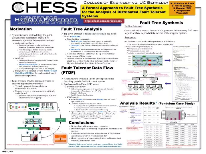
ECU0 ECU1 ECU2 specified to be the specified to be the failure of all failure of all actuators in model actuators in model CH0 CH1 Plant SystemFault SystemFault Top-level event: unrecoverable system failure Sens Act CoarseCTRL Input ArbiterBest Output Sens Logic gates: define Boolean relationships amongst input and output events Act Fine CTRL Mapping +Scheduling Sens Transfer gate: graphical placeholder for sub trees Unable to deliver updated command to the plant from actuator driver c1actm0 on ecu0. Unable to deliver updated command to the plant from actuator driver c1actm1 on ecu2. on ECU ecu0. Coarse CTRL Coarse CTRL ECU0 ECU0 Sens Act Act Sens CH0 CH0 Coarse CTRL Arbiter Best ECU1 ECU1 Coarse CTRL Arbiter Best Sens Input Output Sens Input Output c1actm0(ecu0)Fault c1actm0(ecu0)Fault c1actm1(ecu2)Fault c1actm1(ecu2)Fault CH1 CH1 Basic events: initiating events Fine CTRL Arbiter Best Fine CTRL Arbiter Best ECU2 ECU2 Sens Input Output Act Sens Input Output Act Missing input value Missing input value Basic event hardware Basic event hardware Basic event Basic event Cannot fire actor Cannot fire actor Basic event hardware Basic event hardware Basic event Basic event (assuming fail silence) on (assuming fail silence) on failure of actuator failure of actuator failure of actuator failure of actuator hardware failure hardware failure c0ou1b located on c0ou1b located on hardware failure hardware failure input port ?i0 of actor input port ?i0 of actor c1actm0 located on ECU c1actm0 located on ECU c1actm1 located on ECU c1actm1 located on ECU c1actm0 located on ECU c1actm0 located on ECU ecu0. ecu0. ecu2. ecu2. of ECU ecu0. of ECU ecu0. ECU ecu2. ECU ecu2. of ECU ecu2. of ECU ecu2. ecu0. ecu0. IE IE IE IE R R IE IE IE IE R R Input(?i0)Ofc1actm0(ecu0)Fault ecu0ECU_FAULT ecu0ECU_FAULT c0ou1b(ecu2)Fault c0ou1b(ecu2)Fault ecu2ECU_FAULT ecu2ECU_FAULT c1actm0(ecu0)HW_FAULT c1actm0(ecu0)HW_FAULT c1actm1(ecu2)HW_FAULT c1actm1(ecu2)HW_FAULT (P : 2) (P : 2) Fault behavior +Constraints Functionality (control algorithm using FTDF) Architecture Revisit the Design Other Analysis Techniques Dependability Analysis Timing Analysis Fault tree synthesis Metric Scores Fault tree analysis Synthesis-based design flow with integrated analysis techniques to enable design exploration. • M. McKelvin, G. Eirea • C. Pinello (GMBL), • S. Kanajan (GM) • Sangiovanni- • Vincentelli A Formal Approach to Fault Tree Synthesis for the Analysis of Distributed Fault Tolerant Systems http://chess.eecs.berkeley.edu Fault Tree Synthesis • Problem Statement: • Given a redundant mapped FTDF schedule, generate a fault tree using fault event logic to analyze dependability metrics of the mapped system. • Assumptions: • A fault event in nodes of a FTDF graph results in fail silence • Fail silence: produces correct results or produces no results at all • Fault events are generated due to: • ECU (electronic control unit) fault • Communication channel fault • Actuator or sensor fault (denoted as basic events) • Motivation • Synthesis-based methodology for quick design space exploration enabled by automatic synthesis followed by analysis • Automatic synthesis: • Designer specifies control algorithm, fault behavior, constraints, and selects architecture • Synthesis engine deduce necessary process replication, distribute each process onto architecture, and derives a fault tolerant schedule satisfying constraints • Analysis: • Timing verification/analysis (worst case execution time, time out values) • Dependability analysis (i.e. mean-time-to-failure rate, sensitivity, minimal cutsets, etc.) • Analysis metrics provide hints to the designer • Design flow is centered around Fault Tolerant Data Flow (FTDF) as the mathematical model (model of computation) • Fault trees are models commonly used to analyze dependability metrics • Typically generated manually from requirement documents • Manual process is time consuming, difficult, and informal • Increases turn-around time to analyze fault trees of different system mappings • Fault Tree Analysis • Top-down approach to failure analysis using a tree model called a fault tree • Static fault tree components: • Top-level event: root of tree that represents an undesirable, unrecoverable system failure, as specified by designer • Logic gates: define Boolean relationships amongst input and output events • Basic events: leaves of tree that represents initiating events in the architecture (ECU, channel, sensor, and actuator faults) • A fault tree determines all the ways the top-level event may occur in terms of basic events • Common tools can be used to derive dependability metrics from a fault tree, i.e. Item Toolkit (Item Software), Galileo (Univ. of Virginia), Relex Fault Tree (Relex Software Corp), etc. Fault Tree Generation Algorithm • Fault Tolerant Data Flow • (FTDF) • A mathematical formalism (model of computation) for describing periodic feedback control systems • Synchronous Data Flow (SDF) variant • Deterministic behavior • SDF actor requires presence of all inputs to execute (fire), i.e. firing rule for a 3-input actor: U = {(*, *, *)} • Statically schedulable • Suitable for periodic algorithms • FTDF specific • Actors are typed and annotated with criticality level (i.e. sensor, input, arbiter, etc.) • Communication media are one-place buffers • May have fan-in (inputs) from redundant sources (replicas) • Manages redundant sources and destinations • An abstraction for error detection and recovery • Input and Arbiter type actors may have partial firing rules, i.e. for a 3-input Arbiter actor, firing rule U = {(*,*,*), (┴,*,*), (*,┴,*), (*,*,┴)} specifies the actor may fire if 2-out-of-3 inputs are present (Note: “┴” means not present, “*” means present) Mapped FTDF schedule of the pendulum example. Sample fault generated by fault tree synthesis given in graphical format. Analysis Results*(Pendulum Case Study) • Conclusions • Design flow enables design space exploration • Different designs can be quickly analyzed and offer hints to the designer • Enables formal specification and verification of fault tolerant systems using a correct-by-construction flow • Greater separation of concerns (application, architecture, fault behavior), hence model reuse Designer specified fault behavior for different mappings and dependability metrics. Minimal cutset for mapping 1. This analysis identifies the minimal combination of events that leads to a system failure. • * Graphical fault tree and analysis results were generated by the Item Toolkit courtesy of Rick Clemons and Joe Wysocki of Hughes Research Laboratory. Sensitivity metric (using Barlow Proschan Importance) for each basic event per mapping. May 11, 2005