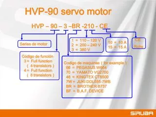
Download
1 / 18
180 likes | 374 Views
CHAPTER 10. Bipolar Junction Transistors: Operation, Circuit Models, and Applications. AC Power. Figure 10.1. Controlled-source models of linear amplifier transistor operation. Figure 10.1. 10-1. Figure 10.2. Models of ideal transistor switches. Figure 10.2. 10-2. Figure 10.4.

E N D
CHAPTER10 Bipolar Junction Transistors: Operation, Circuit Models, and Applications AC Power
Figure 10.1 Controlled-source models of linear amplifier transistor operation Figure 10.1 10-1
Figure 10.2 Models of ideal transistor switches Figure 10.2 10-2
Figure 10.4 Bipolar junction transistors Figure 10.4 10-3
Flow of emitter electrons into the collector in an npn BJT Figure 10.5, 10.6 Current flow in an npn BJT Figure 10.5 Figure 10.6 10-4
Figure 10.7, 10.8 Definition of BJT voltages and currents Figure 10.7 The BE junction open-collector curve Figure 10.8 10-5
Figure 10.9 (a) Ideal test circuit to determine the i-v characteristic of a BJT (b) The collector-emitter output characteristics of a BJT Figure 10.9a Figure 10.9b 10-6
Figure 10.10 Determination of the operation region of a BJT Figure 10.10 10-7
Figure 10.13 Load-line analysis of a simplified BJT amplifier Figure 10.13 10-8
Figure 10.15, 10.16 Circuit illustrating the amplification effect in a BJT Figure 10.15 Amplification of sinusoidal oscillations in a BJT Figure 10.16 10-9
Figure 10.20, 10.21 Practical BJT self-bias DC circuit Figure 10.20 DC self-bias circuit represented in equivalent-circuit form Figure 10.21 10-10
An npn BJT small – signal model ; input impedance ; output admittance ; forward current ratio ; reverse voltage ratio Hybrid-parameter (h-parameter) small-signal model for BJT
; ;
Figure 10.22 An npn BJT large-signal model Figure 10.22 10-11
Figure 10.24, 10.25 LED driver circuit
Figure 10.30 BJT switching characteristic Figure 10.30 10-12
Figure 10.31, 10.32 TTL NAND gate Figure 10.32 Figure 10.31 10-13


![G6 - CIRCUIT COMPONENTS [3 exam question - 3 groups]](https://cdn0.slideserve.com/528131/g6-circuit-components-3-exam-question-3-groups-dt.jpg)