Download
1 / 42
830 likes | 1.56k Views
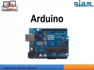
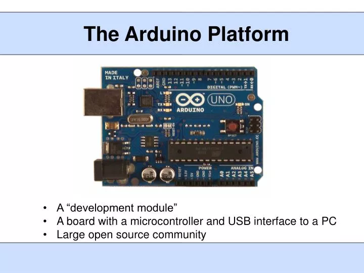
The Arduino Platform. A “development module” A board with a microcontroller and USB interface to a PC Large open source community. Arduino Environment. A development board - 8-bit microcontroller - programming hardware - USB programming interface - I/O pins. A software environment

E N D
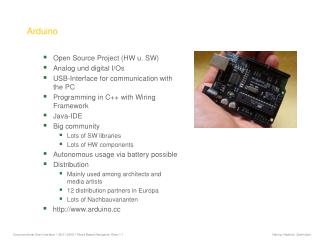
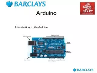
The Arduino Platform • A “development module” • A board with a microcontroller and USB interface to a PC • Large open source community
Arduino Environment A development board - 8-bit microcontroller - programming hardware - USB programming interface - I/O pins A software environment - cross-compiler - debugger - simulator - programmer Special-purpose “shields” - daughter boards - unique functionalities - easy to attach - good libraries provided
Arduino Hardware Typical of an 8-bit processor - low speed, low memory - low cost ($1.50 for the microcontroller, $40 for the board)
Raspberry Pi • 32-bit processor • Broadcom BCM2838 SoC, ARM11 • 700 MHz clock • 512 MB RAM • Broadcom VideoCore IV GPU • SD card slot, no flash built-in • Ports: USB (2), HDMI, RCA audio/video, SD, Ethernet, 2x13 pins • MIPI Camera Interface • Size of a credit card • $35
Raspberry Pi Software • 32-bit machine, can support an operating system • Arch linux, Debian, Fedora, Slackware, etc. • A bit slow for development • Hard to run GUI, IDE • Cross compile with crosstool-ngtoolchainorgcc-linaro-arm-linux • Easy Python programming interface is available
BeagleBone Black • TI Sitara AM3359 ARM Cortex-A8 • 32-bit processor • 1 GHz clock • 512 MB RAM • 2GB on-board flash • 3D graphics accelerator • Ports: USB, Ethernet, HDMI, 2x46 pins • $45 cost, almost the same as an Arduino
Beagle Software Environment • Several versions of linux are ported • Ubuntu, Angstrom, Android … • A bit slow for development • Hard to run GUI, IDE • Cross compile with gcc-arm toolchain • BoneScript (JavaScript) library is provided for simplicity • Uses an interpreter
BeagleBone “Capes” DVI-D Cape VGA Cape Camera Cape • Application-specific, stackable, daughter boards • Just like Arduino shields • Come with libraries
Slides created by: Professor Ian G. Harris UART/USART • Universal Asynchronous Receiver/Transmitter • Used for serial communication between devices • UART is asynchronous, no shared clock • Asynchronous allows longer distance communication • Clock skew is not a problem • USART is the synchronous version of UART • Common clock is needed NVIDIA® Tegra™ 250 NVIDIA® Tegra™ 250
Slides created by: Professor Ian G. Harris Serial Protocols • Data is transmitted serially • Only 1 bit needed (plus common ground) • Parallel data transmitted serially • Original bytes/words regrouped by the receiver • Many protocols are serial to reduce pin usage • Pins are precious
UART Applications • Used by modems to communicate with network • Computers used to have an RS232 port, standard • Not well used anymore, outside of embedded systems • Replaced by USB, ethernet, I2C, SPI • Simple, low HW overhead • Built into most microcontrollers Slides created by: Professor Ian G. Harris
Simple UART Structure Parallel Out Parallel In Tx Rx Serial Out Serial In status status • Data is serialized by Tx, deserialized by Rx • Status indicates the state of the transmit/receive buffers • Used for flow control Slides created by: Professor Ian G. Harris
UART Timing Diagram 8 bits 1 bit • First bit is the Start Bit, initiates the transfer • Next bits are the data • Last are the Stop Bits Slides created by: Professor Ian G. Harris
Bit Duration • Each bit is transmitted for a fixed duration • The duration must be known to Tx and Rx • Baud Rate (f) determines the duration (T) • Baud Rate is the number of transitions per second • Typically measured in “bits per second (bps)” • T = 1/f • Ex. F = 9600 baud, T = ~104 microsec • Transmission rate is less than baud rate • Need start bit, stop bits, parity bit Slides created by: Professor Ian G. Harris
UART Synchronization • Receiver must know the exact start time • Imprecise start time corrupts data Expected Bit, correct bit 7 bit 8 stop stop 1 0 Expected Bit, incorrect bit 7 bit 8 stop Slides created by: Professor Ian G. Harris
Start Bit, Synchronization • Detection of the start bit is used to synchronize • Synchronization based on falling edge of start bit • Start bit is a falling edge • Following 0 must be long duration to screen out noise • Receiver samples faster than baud rate (16x typical) • Start bit is indicated by a 0 of at least half period Start bit detected Just a glitch Slides created by: Professor Ian G. Harris
Parity Bit • Transmission medium is assumed to be error-prone • E-M radiation noise, synchronization accuracy • Parity bit may be transmitted to check for errors • Even Parity: Number of 1’s is even • Odd Parity: Number of 1’s is odd • Parity bit is added to ensure even/odd parity • After data, before stop bit(s) • Ex. Assume Odd Parity, Data = 011011010 • Parity bit = 0, total parity is odd Slides created by: Professor Ian G. Harris
Stop Bit Stop Bit 8 bits 1 bit • Receiver expects a 1 after all data bits and parity bits • If 1 is not received, error has occurred Slides created by: Professor Ian G. Harris
Data Throughput vs. Baud • Every transmission involves sending signaling bits • Stop, start, parity • Data throughput rate is lower than baud rate • Signaling bits must be sent • Ex. 8 data bits, 1 parity bit, baud rate = 9600 • Send 11 bits to send 8 data bits • Transmission efficiency = 8/11 = 73% • Data throughput rate = 9600 * 0.73 = 6981.8 bps Slides created by: Professor Ian G. Harris
USART HW in ATmega • Clock Pin • For synchronous transfers • Output (input) for master (slave) Transmit Pin Receive Pin Slides created by: Professor Ian G. Harris
Clock Generation • Two (or 3) clocks may be needed • Internal Clock – Two internal clocks • High speed clock used by receiver to sample incoming signal • Slower baud rate clock used by transmitter to time transmission • External Clock – Only used in synchronous mode • Baud rate clock used to synchronize master and slave • Generated by master, read by slave Slides created by: Professor Ian G. Harris
Clock Generation Logic Internal TxClk Internal Rx Clk • Rx clk in generated from internal fosc • UBRRn – Prescalar value used to generate Rx clk • UBRRn is two 8-bit registers, UBRRH and UBRRL Slides created by: Professor Ian G. Harris
Clock Operation Modes • Normal Asynchronous • Rx/Txclk rate is 16x baud rate • Accurate sampling of signal, good synchronization • Double Speed Asynchronous • Rx/Txclk rate is 8x baud rate • Double speed transmission, less accurate synchronization • Master Synchronous • Synchronous communication, generate clk • Slave Synchronous • Synchronous communication, receive clk Slides created by: Professor Ian G. Harris
Setting Clocks • High Speed Internal Clock • Internal Rate = fosc / (UBRRn + 1) • Baud Rate Clk, Normal Asynchronous • Baud = fosc / 16 (UBRRn + 1) • Baud Rate Clk, Double Speed Asynchronous • Baud = fosc / 8(UBRRn + 1) Slides created by: Professor Ian G. Harris
Frame Formats • USART has several communication options to define how many bits are transmitted • Start bit: 1 • Data bits: 5 – 9 • Parity bit: none, even, odd • Stop bits: 1 or 2 • Set using bits in the UCSRnBand UCSRnC registers • Format must match on both transmitter and receiver Slides created by: Professor Ian G. Harris
USART Register Summary • UBBR is the prescalar used to determine the clocks • Determines the BAUD rate • UCSRA indicates the status of communications • Transmit/Receive complete, errors, etc. • UCSRB enables interrupts and communications • Interrupt enable, Tx/Rx enable, data size, etc. • UCSRC sets parity bits, stop bits, USART mode, ... • UDR holds transmit data and received data Slides created by: Professor Ian G. Harris
UCSRA • Bit 7 – RXCn: USART Receive Complete • Bit 6 – TXCn: USART Transmit Complete • Bit 5 – UDREn: USART Data Register Empty • Bit 4 – FEn: Frame Error • Bit 3 – DORn: Data OverRun • Bit 2 – UPEn: USART Parity Error Slides created by: Professor Ian G. Harris
Typical USART Initialization #define FOSC 1843200// Clock Speed #define BAUD 9600 #define MYUBRR FOSC/(16*BAUD)-1 void main( void ) {USART_Init( MYUBRR ); } void USART_Init( unsigned intubrr){ /* Set baud rate */ UBRRH = (unsigned char)(ubrr>>8); UBRRL = (unsigned char)ubrr; /* Enable receiver and transmitter */ UCSRB = (1<<RXEN)|(1<<TXEN); /* Set frame format: 8data, 2stop bit */ UCSRC = (1<<USBS)|(3<<UCSZ0); } // USART_Init Slides created by: Professor Ian G. Harris
Transmitting Data void USART_Transmit( unsigned char data ) { // Wait for empty transmit buffer while ( !( UCSRA & (1<<UDRE)) ); // Put data into buffer, sends the data UDR = data; } • Data is transmitted by placing it in the UDRregister • Data Register Empty (UDRE) bit of the UCSRAregister • Set to 0 while a transfer is going on • Need to wait for it before sending new data Slides created by: Professor Ian G. Harris
Receiving Data void USART_Receive( void ) { // Wait for data to be received while ( !( UCSRA & (1<<RXC)) ); // Read data from UDRn buffer return ( UDR ); } • Data is received by reading it from the UDRn register • Different from transmit UDRn register • Receive Complete flag (RXC) bit of the UCSRAregister • Set to 1 when new data is received Slides created by: Professor Ian G. Harris
Communicating with a PC • Need a Terminal Emulator program which “speaks” UART (serial) • There are many free terminal emulators • Hyperterm (used to come with Windows) • Termite • Putty (which I use) • Need to select a COM port to find the USB-to-serial adapter • Need to match frame format to the ATmega Slides created by: Professor Ian G. Harris
Putty Terminal Emulator • Can communicate in several protocols • Select “Serial” • Fill in baud rate • Adjust settings by selecting “Serial” in left column Slides created by: Professor Ian G. Harris
Putty Serial Settings • Flow control • Atmega does not seem to support any Slides created by: Professor Ian G. Harris
UART Uses • UART may be an extra (slow) communication channel • Useful if communication speed is not a problem • Debugging • Make a “print” statement • Note: will alter performance, but not much • Simple User Interface • Humans are slow, interface can be as well Slides created by: Professor Ian G. Harris
Synchronous Communication • Synchronous protocols share a common clock • More accurate, faster than asynchronous protocols • Sampling time is accurately known • Restricted to short range communication • Clock edge and data must have identical timing • Clock edge must arrive at all receivers simultaneously Slides created by: Professor Ian G. Harris
Synchronous Protocols • USART • Limited to communication between two devices (or broadcast) • Serial Peripheral Interface (SPI) • Multi-Drop Bus protocol, more than two devices • Single master, many slaves • Inter-Integrated Circuit (I2C) • Multi-drop, multi-master Slides created by: Professor Ian G. Harris
SPI • a.k.a Four Wire Interface Master Slave MOSI MISO SCLK CS’ MOSI MISO SCLK SS’ • Master Out Slave In (MOSI) –From Master to Slave • Master In Slave Out (MISO) –From Slave to Master • SCLK – Clock generated by Master • Slave Select (SS’) – Indicates communication w/ selected slave • Chip Select (CS’) – Alerts slave to communication Slides created by: Professor Ian G. Harris
SPI Data Transmission • Serial transmission synchronized by the clock • Many bytes may be sent in a single transfer • 8-bits is what we will use • Bi-directional data transmission • MOSI transmits concurrently with MISO • Internal shift register may be used to hold both transmitted and received data • Shift in a received bit, shift out a transmitted bit Slides created by: Professor Ian G. Harris
Clock Polarity and Phase • Clock polarity and phase determine when data is made valid wrt the clock • Polarity = 0 or 1, Phase = 0 or 1 • Data is valid on each clk rising edge or each clk falling edge • Data valid edge (V) = PHASE XOR POLARITY • Polarity = 0, Phase = 0: Rising edge sampling • Polarity = 1, Phase = 1: Rising edge sampling • Polarity = 0, Phase = 1: Falling edge sampling • Polarity = 1, Phase = 0: Falling edge sampling Slides created by: Professor Ian G. Harris
SPI Timing Diagrams SCLK MOSI SS’/CS’ • Polarity, Phase = 0, 0 or 1, 1 bit3 bit3 bit1 bit1 bit2 bit2 SCLK MOSI SS’/CS’ • Polarity, Phase = 0, 1 or 1, 0 Slides created by: Professor Ian G. Harris
Multiple Independent Slaves • Need a unique SS’ for each slave Slave Master MOSI MISO SCLK SS1’ SS2’ SS3’ MOSI MISO SCLK CS’ MOSI MISO SCLK CS’ MOSI MISO SCLK CS’ Slides created by: Professor Ian G. Harris
SPI on the ATmega • Only one SS’ line • SPDR • Reading accesses last received transmission • Writing automatically sends a the data • Do not directly access the SPI pins • Handled in hardware Slides created by: Professor Ian G. Harris