Download

1 / 20
0 likes | 6 Views
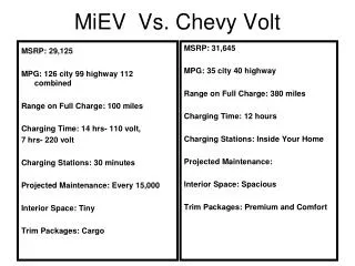
On Prosource get Chevy Intercooler Upgrade Kit in a very affordable range. <br>https://prosourcediesel.com/

E N D
Owner’sManual with Installation Instructions Banks Techni-Cooler® Charge-Air Cooler System 2001-2005 Chevy/GMC Turbo-Diesel Pickup Trucks THIS MANUAL IS FOR USE WITH SYSTEMS 25976, 25977, 25978 Gale Banks Engineering 546 Duggan Avenue • Azusa, CA 91702 (626) 969-9600 • Fax (626) 334-1743 Product Information & Sales: (888) 635-4565 Customer Support: (888) 839-5600 Installation Support: (888) 839-2700 bankspower.com 06/16/16 PN 96784 v.7.0 ©2016 Gale Banks Engineering
General Installation Practices falling. When using ramps, be sure the front wheels are centered squarely on the topsides. When raising the front of the vehicle, put the transmission in park (automatic) or reverse (manual), set the parking brake, and block the rear wheels. When raising the back of the vehicle, be sure the vehicle is on level ground and the front wheels are blocked securely. CAUTION! Do not use floor jacks to support the vehicle while working under it. Do not raise the vehicle onto concrete blocks, masonry or any other item not intended specifically for this use. 6. During installation, keep the work area clean. Do not allow anything to be dropped into intake, exhaust, or lubrication system components while performing the installation, as foreign objects will cause immediate engine damage upon start-up. TOOLS REQUIRED: • Drive ratchet • Ratchet extension • Inch and metric deep sockets • Pliers • Phillips and flat blade screwdrivers • Torx bits Highly recommended tools: • Foot-pound torque wrench • Inch-pound torque wrench Dear Customer, If you have any questions concerning the installation of your Banks Techni-Cooler, please call our Technical Service Hotline at (888) 839-2700 between 7:00 am and 4:00 pm (PT). If you have any questions relating to shipping or billing, please contact our Customer Service Department at (888) 839-5600. Thank you. 1. Before starting work, familiarize yourself with the installation procedure by reading all of the instructions. 2. Throughout this manual, the left side of the vehicle refers to the driver’s side, and the right side to the passenger’s side. 3. Disconnect the negative (ground) cable from the battery (or batteries, if there are two) before beginning work. 4. Route and tie wires and hoses a minimum of 6” away from exhaust heat, moving parts and sharp edges. Clearance of 8” or more is recommended where possible. 5. When raising the vehicle, support it on properly weight-rated safety stands, ramps or a commercial hoist. Follow the manufacturer’s safety precautions. Take care to balance the vehicle to prevent it from slipping or 296784 v.7.0
Intercooler Assembly Installation 1. Disconnect the ground cables from both the driver and passenger side batteries. Position the loose cables so that they do not come into contact with their respective battery posts during the installation. 2. Disconnect the mass airflow (MAF) sensor’s connector at the air box assembly. Loosen the hose clamp at the inlet tube to the turbocharger and disconnect the tube from the turbocharger. Pull the air box out of the vehicle. It’s held in place by plastic fasteners that snap in place. Cover the turbocharger inlet with a clean rag to prevent debris from entering the turbocharger that could result in damage upon start-up. 3. Remove the upper grill baffle that mounts between the grill and radiator cross brace. The baffle is held in place by 7 push-in retainers. The retainers are removed by pulling up on the center pin, then prying the retainer out of it’s hole as shown in Figure 1. 4. Remove the grill a.2001 to 2002 vehicles: The grill is retained by (4x) 1⁄4 turn fasteners, (1x) screw at the latch support, and (2x) snaps at the outboard ends of the grill. Depress the snaps at the ends of the grill before attempting to remove the grill from the vehicle. b.2003 to 2005 vehicles: Disengage the snaps at the outboard ends of the grill. Pull the grill from the vehicle. 5. Rotate the headlamp-retaining pin, then remove the pin as shown in Figure 2. NOTE: Figure 2 shows a 2004 model year vehicle; earlier model years may have two vertical pins per headlamp assembly. 6. Disconnect the connectors from the backside of the headlamp assembly, and remove from the vehicle. Repeat for the driver and passenger side headlamp assemblies. Figure 1: Removal of push-in retaining pins 96784 v.7.03
Figure 2: Headlamp assembly removal Figure 3: Parking lamp assembly removal 496784 v.7.0
7. Remove the park/turn signal lamp assembly by depressing the outboard retaining clip, then rotating the assembly outward as shown in Figure3. The headlamp is easily disengaged and does not require force to be removed once the outboard clip has been depressed. 8. Remove the bulbs from the turn signal lamp assembly by turning the lamp sockets a quarter turn counter- clockwise. 9. Remove the plastic headlamp mounting structure on the driver and passenger side of the vehicle shown in Figure 4. There are (6x) bolts, (2x) torx head bolts, (1x) push- in retainer and (1x) large clip that must be disconnected to remove the piece from the vehicle, per side. The plastic piece that resides by the bumper must be detached from the headlamp mounting structure, but will remain on the vehicle. The retaining clip that attaches the hood latch cable to the support structure must also be removed on the driver’s side. 10. Remove the four bolts that secure the upper fan shroud to the upper radiator cross brace. Remove the four push-in retainers (2 per side) that attach the upper section to the lower section of the fan shroud. These retainers are removed by pulling up on the center pin then prying the entire retainer assembly out as shown in Figure 1. 11. Remove the upper section of the fan shroud from the vehicle. Take care not to damage the face of the radiator when removing the shroud. 12. Remove the two upper condenser mounting bolts that attach to the radiator cross brace. Figure 4: Removal of headlamp/parking lamp assembly support structures 96784 v.7.05
13. Mark the location of the hood latch, then remove the hood latch from the latch support. The latch is held in place by three bolts. The latch support is shown in Figure 4. It is not necessary to remove the cable from the latch, just place the latch and cable assembly out of the way. 14. Remove the two bolts that attach the latch support to the radiator cross brace and the 4 lower attachment bolts (2 per side). The two bolts that attach the upper support to the radiator cross brace are accessed from the engine compartment side of the vehicle. 15. Remove the oil-cooler-line retaining clip as shown in Figure 5. 16. Swing the latch support forward as shown in Figure 6. 17. Pull the air conditioning condenser out of it’s lower mounts, and place it against the latch support. 18. Remove the two upper Charge Air Cooler (CAC) mounting bolts and unfasten the fender support rod from the cross brace as shown in Figure 7. 19. Remove the 6 bolts (3 per side) that secure the radiator cross brace. The cross brace is shown in Figure 7. The bolts are on the bottom side at each end of the support. Remove the cross brace from the vehicle. 20. Remove the air box mounting tray from the vehicle shown in Figure 8. 21. Remove the air box support bracket shown in Figure 9. There is an a/c condenser line retaining clip and a plastic fastener that attaches to the inner fenderwell that must be removed before the bracket can be liberated from the vehicle. 22. Trim the air box support bracket per the template in Figure 10. Figure 11 shows the bracket before and after trimming. Figure 5: Oil cooler line retaining clip 696784 v.7.0
Figure 6: Latch support moved out of the way Figure 7: Upper Charge Air Cooler (CAC) attachment bolt 96784 v.7.07
Figure 8: Air box mounting tray Figure 9: Air box support bracket 896784 v.7.0
This page left blank intentionally 96784 v.7.09
Fig 10. Trim template for the air box-mounting bracket. TRIMBRACKETALONGTHISLINE ALIGNWITHBRAKET BEND TRIMB RACKETALONGTHISLINE BRACKETEDGE ALIGNWITH ALIGNWITH BRAKETCORNER 1096784 v.7.0
TRIMBRACKETALONGTHISLINE ALIGNWITHBRAKET BEND TRIMB RACKETALONGTHISLINE BRACKETEDGE ALIGNWITH 96784 v.7.011
This page left blank intentionally 1296784 v.7.0
Fig 11. Before and after removing material from the air box support bracket. Figure 12: Radiator attachment bolt and lower clamp 96784 v.7.013
23. Remove the 8 pushpin fasteners and 2 large head plastic fasteners that attach the driver’s side fenderwell. The fasteners are accessed through the wheel arch opening. Pull the fenderwell down approximately 6 inches once the fasteners are removed. Disconnect the wire harness retaining clips on top of the fenderwell, then remove the fenderwell from the vehicle. 24. Loosen the driver and passenger side boost tube attachment hoses. Do not damage the hoses that attach to the charge air cooler (CAC) as they will be re-used. Remove the boost tubes and hoses from the vehicle. The driver side boost tube should be removed through the fenderwell and the passenger side upward through the engine compartment. Cover the intake manifold and turbocharger discharge to prevent foreign debris from entering during the installation. 25. Remove the radiator attachment bolts and the lower retaining clamps shown in Figure 12. 26. Lift the radiator out of it’s lower saddle mounts and position it towards the engine so that it is no longer attached to the charge air cooler. Take care not to damage the radiator cooling fins. 27. Remove the charge air cooler from the vehicle. Check that the lower mounting peg grommets remained in the vehicles frame. Return them to their home on the vehicles frame, if they came out with the charge air cooler. 28. Remove the metal sleeve from the upper CAC isolation grommets. Remove the grommets from the stock charge air cooler and place them on the Banks charge air cooler. Reinstall the metal sleeves in the Banks charge air cooler in the same orientation as they were removed from the stock CAC. Figure 13: Gap between the CAC hose stop and radiator end tank 1496784 v.7.0
Figure 14: Lower fan shroud fitment with the radiator 29. Remove the lower radiator saddle mount grommets from the stock CAC and install them on the Banks CAC. 30. Place the Banks CAC in the vehicle. Align the lower CAC mounting pegs with the rubber mounts in the vehicle’s frame. There is a significant amount of play in the rubber mounts that can allow them to be aligned with the CAC as required. 31. Reinstall the radiator into the lower saddle mounts of the Banks CAC. 32. Reinstall the radiator cross brace. Leave the attachment bolts loose to aid in aligning the CAC with the support. 33. Install the upper CAC attachment bolts that were previously removed. There is enough play in the lower mounting pads, that the CAC can be positioned to align with the upper cross brace. Tighten the bolts. 34. Position the radiator so that it’s centered on the CAC. Check the gap between the hose stops on the CAC and the radiator end tanks on each side of the CAC. Reposition the radiator relative to the CAC until the gap is equal on each side. The location to check is shown in Figure 13. 35. Check that the engine cooling fan can freely spin without contacting the lower fan shroud. If the fan contacts the shroud, the shroud must be re-aligned with the radiator. The correct alignment is shown in Figure 14. Each side of the shroud should overlap the radiator headers, and the mounting tabs should fit into their respective bosses as shown in Figure 14. 36. Secure the radiator to the Banks CAC with the 5⁄16”-18 by 1.0” long bolts and large OD washers that were supplied with the Banks system. Tighten to 10-12 ft-lbs. 96784 v.7.015
37. Install the lower driver side radiator-retaining clamp that was removed from the stock CAC and secure with the 5⁄16”-18 by 0.5” long bolts and the smaller OD washers that were supplied with the Banks system. Tighten to 10-12 ft-lbs. The passenger side clamp will contact the battery support bracket, and is optional to reinstall. 38. Tighten the 6 radiator cross brace bolts to 80 in-lbs. Install the diagonal fender support brace and tighten the bolts. 39. Insert the supplied round metal spacers into the rubber shroud gasket as shown in Figure 15. The spacers should be inserted so that the step mates with the cross brace. 40. Install the upper fan shroud. The supplied gasket is used to fill the gap between the shroud and the cross brace. The push-in retainers that secure the upper shroud to the lower shroud are secured by inserting the retainer with the center pin pulled out. Once the retainer is inserted, press the center pin down to secure the retainer. Install the gasket and upper fan shroud bolts. The stock upper fan shroud bolts are reused and should be tighten to 80 in-lbs. 41. Install the a/c condenser and tighten it’s upper mounting bolts to 80 in-lbs 42. Install the latch support. Tighten it’s six attachment bolts to 80 in-lbs. Install the oil-cooler-line retaining clip shown in Figure 5. 43. Install the hood latch. Position it so that it aligns with the marks that were previously made on the latch support prior to it’s removal. Tighten it’s bolts to 80 in-lbs. 44. Install the driver and passenger side plastic headlamp support structures. Tighten the screws to 80 in-lbs. Figure 15: Metal spacers installed in the shroud gasket 1696784 v.7.0
45. Install the light bulbs into the park/turn signal lamp assemblies. These are held in place by turning them clockwise. Install the park/turn signal lamp assembly onto the vehicle for both the driver and passenger side. 46. Install the electrical connectors to the headlamp assembly. Install the headlamp assemblies and secure them with their retaining pins. 47. Install the grill: a.2001 to 2002 vehicles: The grill is retained by (4x) 1⁄4 turn fasteners, (1x) screw at the latch support, and (2x) clips at the outboard ends of the grill. Tighten the screw at the latch support to 75 in-lbs. b.2003 to 2005 vehicles: The grill is held in place by retaining clips, and can be snapped in place. 48. Install the upper grill baffle and secure with the seven push- in retainers that were previously removed. The push-in retainers that secure the grill baffle are secured by inserting the retainer with the center pin pulled out. Once the retainer is inserted, press the center pin down to secure the retainer. NOTE: Before slipping any boost tubes and the corresponding hoses, into position, ensure that all connection ends are clean and free of any oil residue and contaminates. Clean compressor outlet and all connection points with a non-oil based solvent such as Acetone, Mineral Spirits, Denatured Alcohol or Lacquer Thinner. Read and follow the manufactures operation instruction for non-oil based solvent cleaner. Figure 16: Spring hose clamps 96784 v.7.017
49. Install the driver and passenger side boost tubes. New clamps are provided for the intake manifold hose to boost tube connection and the turbo hose to boost tube connection. All other locations reuse the factory clamps. Tighten the clamps to 75 in-lbs. The following hoses are used at each location: 2001 vehicles: Turbocharger outlet: 3 inch to 23⁄8 inch ID straight reducer (PN# 94291) CAC inlet (driver side): Re-use factory hose CAC outlet (passenger side): Uniform 3 inch ID with 145-degree bend (PN# 94294) Intake manifold: 3 inch to 23⁄8 inch ID with 120-degree bend (PN# 94274) 2002 to 2004 LB7 vehicles: Turbocharger outlet: 3 inch to 23⁄8 inch ID straight reducer (PN# 94291) CAC inlet (driver side): Re-use factory hose CAC outlet (passenger side): Re-use factory hose Intake manifold: 3 inch to 23⁄8 inch ID straight reducer (PN# 94291) NOTE: The a/c line that runs near the intake manifold will need to be bent downward to provide clearance for the boost tube. The line can be bent by placing a wooden block on the a/c line, then lightly tapping the block with a hammer. Rotate self-tightening spring hose clamps on fuel filter away from Banks turbo charge outlet boost hose. See Figure 16. 2004.5 to 2005 LLY vehicles: Turbocharger outlet: 3 inch to 23⁄8 inch ID straight reducer (PN# 94291) CAC inlet (driver side): Re-use factory hose CAC outlet (passenger side): Uniform 3 inch ID with 145-degree bend (PN# 94294) Intake manifold: 3 inch to 23⁄8 inch ID with 120-degree bend (PN# 94295) 50. Install the driver side fenderwell. The charge air temperature before the CAC approaches 400˚F at full load. So, take care to route wiring away from the driver side boost tube and re-install the factory wire retainers on the fenderwell cover. 51. Install the lower air cleaner support bracket. Tighten the bolts to 80 in-lbs. Install the air cleaner mounting tray. Tighten the bolts to 80-in-lbs. 52. Install the air box assembly on it’s mounting tray. Install the air duct on the turbocharger inlet and tighten it’s hose clamp. 53. Re-install the connector on the MAF sensor at the air box assembly 54. Re-connect the ground cables on both batteries. 55. Clean an area that is easily visible on the upper radiator core support with a non-oil based solvent, such as Acetone, Mineral Spirits, Denatured Alcohol or Lacquer Thinner. Allow to dry and then attach the Banks E.O. sticker to the upper radiator core support. NOTE: For 2001 models, attach Banks E.O. label D-161-82. For all other models, attach Banks E.O. label D-161-83 1896784 v.7.0
Gale Banks Engineering 546 Duggan Avenue • Azusa, CA 91702 (626) 969-9600 • Fax (626) 334-1743 Product Information & Sales: (888) 635-4565 Customer Support: (888) 839-5600 Installation Support: (888) 839-2700 bankspower.com