Download
1 / 16
160 likes | 163 Views
Learn about flow control and error control in data link protocols. Understand how flow control prevents buffer overflow and how error control detects and corrects transmission errors.

E N D
ITC242 – Introduction to Data CommunicationsWeek 10Topic 16 Data link control
Last Week Data Transmission • Describe the difference between analogue and digital signals • Transmission impairments – attenuation and noise affect signal quality • Shannon’s formula provides a theoretical estimate of maximum channel capacity
Last Week Data Communication Fundamentals • The difference between analogue and digital transmission • Digital and analogue encoding techniques: • ASK, FSK, PSK • NRZ-L, NRZI, Manchester, Differential Manchester • Asynchronous transmission • Synchronous transmission
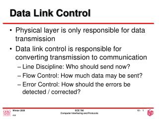
Topic 16 – Data link control Learning Objectives • Describe flow control and error control
Flow Control • Necessary when data is being sent faster than it can be processed by receiver • Computer to printer is typical setting • Can also be from computer to computer, when a processing program is limited in capacity
receive side of TCP connection has a receive buffer: speed-matching service: matching the send rate to the receiving app’s drain rate flow control sender won’t overflow receiver’s buffer by transmitting too much, too fast TCP Flow Control • app process may be slow at reading from buffer
(Suppose TCP receiver discards out-of-order segments) spare room in buffer = RcvWindow = RcvBuffer-[LastByteRcvd - LastByteRead] Rcvr advertises spare room by including value of RcvWindow in segments Sender limits unACKed data to RcvWindow guarantees receive buffer doesn’t overflow TCP Flow control: how it works
Error Control Process • All transmission media have potential for introduction of errors • All data link layer protocols must provide method for controlling errors • Error control process has two components • Error detection • Error correction
Error Detection: Parity Bits • Bit added to each character to make all bits add up to an even number (even parity) or odd number (odd parity) • Good for detecting single-bit errors only • High overhead (one extra bit per 7-bit character=12.5%)
Error Detection • EDC= Error Detection and Correction bits (redundancy) • D = Data protected by error checking, may include header fields • Error detection not 100% reliable! • protocol may miss some errors, but rarely • larger EDC field yields better detection and correction otherwise
Parity Checking Two Dimensional Bit Parity: Detect and correct single bit errors Single Bit Parity: Detect single bit errors 0 0
Sender: treat segment contents as sequence of 16-bit integers checksum: addition (1’s complement sum) of segment contents sender puts checksum value into UDP checksum field Receiver: compute checksum of received segment check if computed checksum equals checksum field value: NO - error detected YES - no error detected. But maybe errors nonetheless? Internet checksum (review) Goal: detect “errors” (e.g., flipped bits) in transmitted packet (note: used at transport layer only) Complement: 1011010100111101 1011101101010101 1000111100001100 0100101011000010 0110011001100000 0101010101010101 1011101110110101 0110011001100000 0101010101010101 1000111100001100 1111111111111111
Error Detection: Cyclic Redundancy Check (CRC) • Data in frame treated as a single binary number, divided by a unique prime binary, and remainder is attached to frame • 17-bit divisor leaves 16-bit remainder, 33-bit divisor leaves 32-bit remainder • For a CRC of length N, errors undetected are 2-N • Overhead is low (1-3%)
Checksumming: Cyclic Redundancy Check • view data bits, D, as a binary number • choose r+1 bit pattern (generator), G • goal: choose r CRC bits, R, such that • <D,R> exactly divisible by G (modulo 2) • receiver knows G, divides <D,R> by G. If non-zero remainder: error detected! • can detect all burst errors less than r+1 bits • widely used in practice (802.11 WiFi, ATM)
CRC Example Want: D.2r XOR R = nG equivalently: D.2r = nG XOR R equivalently: if we divide D.2r by G, want remainder R D.2r G R = remainder[ ]
Error Correction • Two types of errors • Lost frame • Damaged frame • Automatic Repeat reQuest (ARQ) • Error detection • Positive acknowledgment • Retransmission after time-out • Negative acknowledgment and retransmission