Download
1 / 17
170 likes | 291 Views
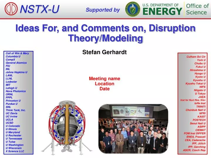
NSTX-U. Supported by. Ideas For, and Comments on, Disruption Theory/Modeling. Stefan Gerhardt. Coll of Wm & Mary Columbia U CompX General Atomics FIU INL Johns Hopkins U LANL LLNL Lodestar MIT Lehigh U Nova Photonics ORNL PPPL Princeton U Purdue U SNL Think Tank, Inc.

E N D
NSTX-U Supported by Ideas For, and Comments on, Disruption Theory/Modeling Stefan Gerhardt Coll of Wm & Mary Columbia U CompX General Atomics FIU INL Johns Hopkins U LANL LLNL Lodestar MIT Lehigh U Nova Photonics ORNL PPPL Princeton U Purdue U SNL Think Tank, Inc. UC Davis UC Irvine UCLA UCSD U Colorado U Illinois U Maryland U Rochester U Tennessee U Tulsa U Washington U Wisconsin X Science LLC Culham Sci Ctr York U Chubu U Fukui U Hiroshima U Hyogo U Kyoto U Kyushu U Kyushu Tokai U NIFS Niigata U U Tokyo JAEA Inst for Nucl Res, Kiev Ioffe Inst TRINITI Chonbuk Natl U NFRI KAIST POSTECH Seoul Natl U ASIPP CIEMAT FOM Inst DIFFER ENEA, Frascati CEA, Cadarache IPP, Jülich IPP, Garching ASCR, Czech Rep Meeting name Location Date
ToC • About the NSTX 5-Year plan for disruptions. • A cautionary note on NSTX disruptions • A major disruption example that might be amenable to modeling. • Comments on NSTX halo current measurements and “experimentalist driven” ideas for further research. • Trying to follow Amitava’s admonition to look for short term projects. • Not including RWMs, NTM, LMs, and other “initiating events” typically studied by CU group, J.-K. Park, JEM, GA,...
Disruptions are the Explicit Focus of 1 in 3 Elements of the MHD NSTX-U Five Year Plan, and 1 in 4 of ASC Plan • Other two MHD topics focus on MHD mode physics/control and 3D field effects. • Within MHD disruption thrust, there are three sub-elements: • ST1: Control aspects of disruption avoidance. • ST2: Disruption mitigation: • Development of new MGI valves. • Understanding how the neutral gas propagates through the SOL & edge pedestal and into the main plasma (DEGAS-2). • Understanding the importance of poloidal injection location in setting the assimilation rate. • Testing novel mass injection technologies (EPI) • ST3: Disruption physics: • Improve projection of thermal quench characteristics/loading for next-step STs. • Develop an understanding of halo current dynamics. • ASC chapter calls for parallel research in the area of disruption precursor detection and controlled discharge shutdown. • This using traditional shape and IP control, in contrast to mitigation by mass injection.
Most Disruptions in NSTX Were “Complicated” • Flat-Top Phase • Well diagnosed (in general). • Provides the “initial condition” for the RWM/LM/whatever and subsequent disruption process. • Pre-Disruption Phase • Initiated by RWM/LM/whatever. • Dynamics include H->L back transitions, position/shape/IP/RWM control dynamics, internal reconnections,… • Actual Disruption • Initiated by TQ, followed by CQ. • HCs flow. • Plasma almost always severely displaced from the midplane…limits measurements. Well diagnosed flat-top phase typically temporally isolated from actual disruption.
Unique Class of Major Disruptions Identified in NSTX • Recipe: • Generate a stable low(er) q95 discharge. • Run it to the current limit of the OH coil. • Ramp the OH coil back to zero, applying a negative loop voltage, while leaving the heating on. • Watch li increase, then disruption occurs. • Mechanism responsible for 21 for the 22 highest WMHD disruptions in NSTX. • Specific example in the general area of how unstable current profiles lead to catastrophic instability
Disruption Shows Some Multi-Timescale Features That May Be Modelable • Clear drop in edge profiles before the core. • Clear ~1.5 ms time separation between the events. • Could be examined with extended MHD codes? • Reproduce the edge collapsing before the core? • Reproduce the time-scales? • MSE constrained equilibria available for the phase before the rampdown is initiated. • Buy may need to evolve the equilibrium once Vloop is reversed.
Strongly Non-Axisymmetric Halo Currents Detected in the NSTX Lower Divertor 141687 Row 3 • Measurements from an array of instrumented tiles • Same poloidal angle • Distributed toroidally • Infer strong toroidal asymmetry, often with significant rotation, at locations where currents enter the divertor floor. 300 200 100 0 Toroidal Angle f [degrees] 0.408 0.410 0.412 0.414 Time [s] Tiles 10
Li I Camera Images Confirm Rotation of Structure Four Times • Neutral lithium light most indicative of surface interactions
Use a Model Fit Function To Better Resolve the Halo Current Dynamics Model Function “Windowed Cosine Power Fits” • Observed structure is a toroidally localized lobe. • Apply a fit function with • DC offset (f0) • lobe of variable toroidal width (f4) and amplitude (f1) • Explicit rotation frequency (f3) • Divide data into dt~0.1 ms width windows, and fit data from all six tiles during each window. • Fitting windows allows the features to rotate over the tiles during periods of fits. Example Curves Halo Current f(t,f) Toroidal Angle f 12
Dominant Structure of the Halo Current is a Rotating Toroidally Localized Lobe of Current 141687 Row 3 300 200 100 0 Toroidal Angle f [degrees] 0.408 0.410 0.412 0.414 Time [s] max(JHC) min(JHC) f0f1 13
This Example Has an Edge q of ~2 When the Actual Disruption Starts • Tends to be representative…qedge = 2 initiates the final VDE disruption in most cases.
There Is a Class of Disruptions With qedge Well Beneath 2 For a Significant Duration. ITER-critical: sideways forces from AVDEs are critical for ITER…large m/n=1/1 displacement…what are the conditions for qedge approaching 1?
Videos Confirm that the Plasma Resides on the Upper Divertor Before Slamming Downward Onto the Lower SPPs
Key Messages • The halo current pattern is 3D (strongly non-axisymmetric), and can represent a substantial fraction of the plasma current. • There are tantalizing hints about the equilibria of these VDEs before/during the halo current phase, but these reconstructions are not complete in their physics. • Desirable tools: • Routine axisymmetric equivalent reconstructions, allowing for currents outside the separatrix. • Believe it is in EFIT, but not LRDFIT. • Must account for large, potentially 3D, vacuum chamber currents. • How do you treat the halo width? • Fully 3D equilibria. • Though candidly unclear how we would constrain them. • Potential topic: Define a limited, semi-realistic set of halo current sensors or other measurements that are most appropriate for these constraints. • Otherwise, likely to just add more shunt tiles in the fairly obvious pattern discussed before. • For instance, what measurements in the structures would be most important?
So What Is the Difference? qmin~2 VDEs Land on the Lower Divertor qmin<2 VDEs Typically Land on SPPs ITER-critical: sideways forces from AVDEs are critical for ITER…large m/n=1/1 displacement…what are the conditions for qedge approaching 1?