Download
1 / 27
280 likes | 329 Views
OSPF (Open Shortest Path First). Link-state based routing protocol: an Interior Gateway Protocol (IGP) – for inside ASs. What is OSPF?. Open Developed by IETF IGP working group, RFC2328 SPF Each router floods link-state information through its neighbors to other routers

E N D
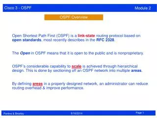
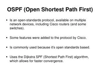
OSPF (Open Shortest Path First) Link-state based routing protocol: an Interior Gateway Protocol (IGP) – for inside ASs
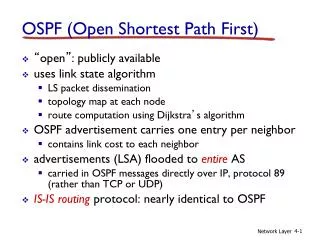
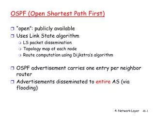
What is OSPF? • Open • Developed by IETF IGP working group, RFC2328 • SPF • Each router floods link-state information through its neighbors to other routers • Based on the flooded link-state information, each router maintains a complete link-state database • Based on the link-state database, a routing table is constructed using SPF (e.g., Dijkstra’s) algorithm • Runs over IP directly, protocol number 89
Features of OSPF • Use flexible metrics instead of only hop count • Supports variable-length subnetting • Allows load balancing among equal-cost paths • Supports multiple routes; one for each IP type of service (ToS) • Authenticates route exchanges • Quick convergence • Uses multicast rather than broadcast of its messages to reduce network load
Hierarchical OSPF • AS is organized as two-level hierarchy • AS is partitioned into self-contained areas • Areas are interconnected by a backbone area • Areas are identified by a 32-bit area ID • 0.0.0.0 is reserved for the backbone area • Four types of routers • Internal router, area border router, backbone router, autonomous system boundary router (ASBR)
OSPF AS organized into a 2-level hierarchy (ASBR) Within each area, border router responsible for routing outside the area Exactly one area is backbone area Backbone area contains all area border routers and possibly others
OSPF packets • Five types of OSPF packets • Hello(1) • Database description(2) • Link-State Request(3)/Update(4)/Acknowledgement(5) • OSPF common header
OSPF common header fields • Version number: 2 • Type: Type of OSPF packet • Packet length: in bytes, includes OSPF header • Router ID: 32-bit number assigned to each OSPF running router – uniquely identifies router within AS • Area ID: any four-byte number (0.0.0.0 reserved for backbone area) • Checksum: error detection • Three Authentication related fields: to authenticate OSPF packets
Hello packet fields • Network mask: Subnet mask of the interface the packet is sent on • Hello interval: Number of seconds between Hello packets • Options: optional capabilities supported by the router • Priority: of the router – used in election of designated router • Dead interval: Number of seconds before declaring a nonresponding neighbor down • Designated router/Backup: Every broadcast network with at least two routers has a designated router. This sends network LSAs for the broadcast network. This field is 0.0.0.0 if there is no designated router • Neighbors: Router ID of each neighbor from whom Hello packets have recently been received
Database description packet • Database description packet • LSA header LSA: Link State Advertisement
Database description packet fields • Interface MTU: MTU of the associated interface • Options: optional capabilities supported by the router • I bit: Init bit set to 1 if this packet is the first in the sequence of database description packets • M bit: More bit is set to 1 if more database description packets are to follow • MS bit: Master/Slave bit • Database description seq. no.: identifies the packet number sequentially so that a receiver can detect a missing packet
LSA header fields • Link-state age: time since LSA generation • Options: optional capabilities supported by the router • Link-state type: router LSA, network LSA, summary LSA for IP networks, summary LSA for ASB routers, AS-external LSAs • Link-state ID: describes routing domain for the LSA; depends on LSA type • Advertising router: router ID of the router that generated the LSA • Link-state sequence number: Numbers LSAs sequentially to identify old and duplicate LSAs • Link-state checksum: entire contents of LSA except link-state age • Length: in bytes of LSA including LSA header
Link-state Request/Update/ Acknowledgement • Link-state Request • Link-state Update • Link-state Acknowledgement
Type #TOS Metric Router LSA 32 bits LSA header 0 0 V E B #links per-link fields Link ID Link Data Repeat per-link fields for each link
LSA fields • bit V (Virtual): 1 when router is a virtual link endpoint • bit E (External): 1 when router is an ASBR • bit B (Border): 1 when router is an area border router • # links: # of links described in this LSA • Per link: • Type: • Point-to-point connection to another router: 1 • Connection to a transit network: 2 • Connection to a stub network: 3 • Virtual link: 4
LSA fields contd. • Per-link: • #TOS: number of TOS metrics other than the required link metric given to this link; if none, 0 • Link ID: Identifies the type of node connected to this link • If type 1, Neighboring router's Router ID • If type 2, IP address of Designated Router • If type 3, IP network/subnet number • If type 4, Neighboring router's Router ID • Link Data: depends upon type of link • For links to stub networks: Network's IP address mask • For point-to-point links: the interface's MIB-II ifIndex value. • For the other link types: the router interface's IP address. • Metric: cost of using this link
Link state updates • Each Link State Update packet carries a set of new link state advertisements (LSAs) one hop further away from their point of origination. A single Link State Update packet may contain the LSAs of several routers. Each LSA is tagged with the ID of the originating router and a checksum of its link state contents.
OSPF operations • Hello protocol • Database synchronization • Propagation of link-state information • Building of routing table
Hello Protocol • Hello packets are transmitted to all interfaces periodically • Discover neighbors, establish and maintain neighbor adjacency relationships • Elect Designated Router (DR) if there are multiple routers in a broadcast network
Database synchronization • Two neighboring routers exchange database description packets to synchronize their link-state databases. • Database description includes only a list of LSA headers. New or more up-to-date LSAs will be requested later • Packets sent by master are acknowledged by slave
Propagation of link-state information • Link-state request sent • When a router wants to update parts of its link-state database • Link-state update sent • When a link state is requested, or • When a link-state changes, or • Periodically • Link-state acknowledgement sent in response to a link-state update • Link-state updates retransmitted periodically until acknowledged
Flooding LSAs • A node receiving a link-state update selectively first installs each LSA in the update into its LSA database • Then it decides on which of its other links to flood the LSA • it may decide not to flood an LSA out a particular interface if there is a high probability that the attached neighbors have already received the LSA.
Building of routing table • Router S has knowledge of the entire area topology (complete link-state database) • Some algorithm such as Dijkstra’s is used to generate shortest path tree, rooted at router S • Only the next hop will be used in the routing table
AREA 1 18.10.0.6 This is the link metric - note NOT hostID Example Assume that all RT3 interfaces have 3 as their host ID Backbone area 192.1.2 3 RT1 N1 1 N3 192.1.1 RT4 3 RT2 N2 1 8 6 RT3 RT6 192.1.3 2 N4 192.1.4 Construct Router LSA for RT3
RT3’s router-LSA for Area 1 • Link to N4: [COMMENT] • Link ID = 192.1.4.0 ; IP Network number • Link Data = 0xffffff00; Network mask • Type = 3; connects to stub network • # TOS metrics = 0 • metric = 2 • LS age = 0; true on origination • Options =; • LS type = 1; indicates router-LSA • Link State ID = 192.1.1.3; RT3's Router ID • Advertising Router = 192.1.1.3; RT3's Router ID • bit E = 0; not an AS boundary router • bit B = 1; area border router • #links = 2 • Link to N3: [COMMENT] • Link ID = 192.1.1.4 ; IP address of Desig. Rtr. • Link Data = 192.1.1.3; RT3's IP interface to net • Type = 2; connects to transit network • # TOS metrics = 0 • metric = 1 Audio asks you to consult slides 10, 12, 14, 24: if new slides are added, these numbers will change, but here are the slide titles slide 10: DDP+ LSA header slide 12: LSA header fields slide 14: Router LSA slide 24: Example
RT3's router-LSA for the backbone • LS age = 0; always true on origination • Options = ; • LS type = 1; indicates router-LSA • Link State ID = 192.1.1.3; RT3's router ID • Advertising Router = 192.1.1.3; RT3's router ID • bit E = 0; not an AS boundary router • bit B = 1; area border router • #links = 1 • Link to RT6 • Link ID = 18.10.0.6; Neighbor's Router ID • Link Data = 0.0.0.3; MIB-II ifIndex of P-P link • Type = 1; connects to router • # TOS metrics = 0 • metric = 8
References • Section 8.7.2 of Communication Networks by A. Leon Garcia and I. Widjaja • RFC 2328 (can be obtained from www.ietf.org)