Download
1 / 17
200 likes | 483 Views
Electrical Properties of SrBi 2 Ta 2 O 9 Thin Films Prepared by r.f. magnetron sputtering. Electro-ceramics laboratory Department of Materials Engineering, Sangju National University, 742-711, Sangu, kyungbuk, Korea. OUTLINE. ▶ Introduction

E N D
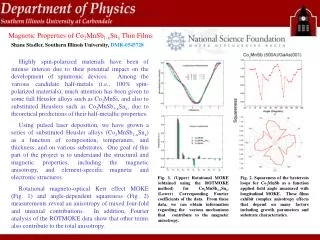
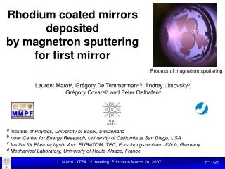
Electrical Properties of SrBi2Ta2O9 Thin Films Prepared by r.f. magnetron sputtering Electro-ceramics laboratory Department of Materials Engineering, Sangju National University, 742-711, Sangu, kyungbuk, Korea
OUTLINE ▶ Introduction Why SrBi2Ta2O9 thin Films ? ▶ Preparation of SBT thin films by PEMOCVD ▶ Formation of oxide interfacial phase at interface between SBT and Pt ▶ Electric Properties of SBT thin films ▶ Summary
Why SrBi2Ta2O9 thin Films ? Ferroelectric thin Films(Especially, PZT) Degradation problems Fatigue Imprint Aging Solution for fatigue Conductive oxide electrode(LSCO, RuO2, IrO2) Doping(La, Nb) Ferroelectric SrBi2Ta2O9 thin Films Bi-layer structure Low intrinsic defect Good ferroelectric switching characteristics Attractive materials for the nonvolatile memory devices Introduction
Deposition parameters SBT by PEMOCVD 500 - 600 oC 130 W 3 cm 2 torr 120 oC 80 sccm 150 oC 80 sccm 130 oC 15 sccm 200 sccm 80 min. MOCVD-Pt/SiO2/Si Pt/Ti/SiO2/Si Deposition temperature RF power Distance between electrodes System pressure Bubbling temperature of Sr(hfa)2(tet) Ar gas flow rate of Sr source Bubbling temperature of Bi(C6H5)3 Ar gas flow rate of Bi source Bubbling temperature of Ta(C2H5O)5 Ar gas flow rate of Ta source O2 gas flow rate Deposition time Substrate Experimental Conditions
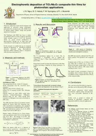
XRD Analysis X-ray diffraction patterns of the SrBi2Ta2O9 films deposited on (a) MOCVD-Pt/SiO2/Si and (b) Pt/Ti/SiO2/Si
XRD Analysis X-ray diffraction patterns of the Bismuth films annealed at 800℃ in oxygen ambient after deposition on Pt/Ti/SiO2/Si at room temperature.
TEM Analysis (a) (b) BTO Pt/Ti SiO2 Cross-sectional TEM images of SBT films deposited on (a) Pt/SiO2/Si (b) Pt/Ti/SiO2/Si
AES Analysis (A) (C) #5 Pt Pt Ti O #4 500nm #3 (B) #2 #1 (A),(B) SEM image and (C) AES spectra of Pt/Ti/SiO2/Si substrates before deposition of SBT thin films
(b) The composition of SBT/Pt interface(35nm thickness) O-33.00 Ta-7.00 Bi-7.00 Pt-40.00Si-5.0000 Ti-8.00 10 7 (a) Si Ti Pt 10 6 Bi Sr0.8 Bi2.0Ta2.0O9 O 10 5 Ta 10 4 Pt Counts / Sec 10 3 Sr Bi Ta 10 2 Si Ti Sr 10 1 0 100 200 300 400 500 10 0 -----Theoretical Experiment 0 500 1000 1500 Sputt. Time (Sec) SIMS and RBS Analysis (a) SIMS depth profile and (b) RBS of the SBT films deposited on Pt/Ti/SiO2/Si
The composition of SBT/Pt interface(35nm thickness) O-33.00 Ta-7.00 Bi-7.00 Pt-40.00 Si-5.0000 Ti-8.00 Pt Sr0.8 Bi2.0Ta2.0O9 Ta Bi Si Ti Sr 0 100 200 300 400 500 Channels Experimental Theoretical RBS Analysis The Composition of SBT films deposited on Pt/Ti/SiO2/Si
er and tan d vs. Temperature Temperature dependence on the dielectric constant and dissipation factor of SBT/Pt/Ti/SiO2/Si films at various frequencies
Leakage Current Density (a) Current-time curve under dc field of 2 V and (b) I-V curve of SBT films with delay time of 1 sec
Schottky Barrier height ln [Δ(J/T2) = qΦB/k[Δ(1/T)] Schottky barrier height :ΦB = ~ 1.2 eV (a) The leakage current density (J) vs. applied voltage of SBT films deposited on Pt/Ti/SiO2/Si as a function of temperature and (b)log (J/T2) vs. 1/T at the various applied voltages.
Schottky Barrier height ln [Δ(J/T2) = qΦB/k[Δ(1/T)] Schottky barrier height :ΦB = ~ 0.8 eV (a) The leakage current density (J) vs. applied voltage of SBT films deposited on Pt/SiO2/Si as a function of temperature and (b) log ( J/T2 ) vs. 1/T at the various applied voltages.
P-E Curves Hysteresis loops of SBT films prepared on (a) MOCVD-Pt/SiO2/Si and (b) Pt/Ti/SiO2/Si substrates
20 80 ) ) Pr*-Pr^ Pr*-Pr^ 2 2 60 10 40 C/cm C/cm 20 m m 0 0 -20 Polarization ( Polarization ( -40 -10 -Pr*-(-Pr^) -Pr*-(-Pr^) -60 -80 -20 10 10 10 10 10 10 10 10 10 10 10 10 10 10 10 10 10 10 10 10 10 10 10 0 1 2 3 4 5 6 7 8 9 10 11 0 1 2 3 4 5 6 7 8 9 10 Switching Cycles Switching Cycles Fatigue Characteristics (a) (b) Fatigue Characteristics of SBT films deposited on (a) MOCVD-Pt/SiO2/Si (b) Pt/Ti/SiO2/Si
Summary ▶ SrBi2Ta2O9 thin films were successfully prepared at 550℃ by Plasma -enhanced MOCVD. ▶ BTO(Bi4Ti3O12) phase were formed at interface between SBT and Pt/Ti/SiO2/Si. ▶ BTO phase decreased the leakage current density of SBT thin films. ▶ Schottky barrier height of Pt/SBT/Pt capacitor ΦB = ~ 0.8 eV without Ti layer ΦB = ~ 1.2 eV with Ti buffer layer ▶ SBT thin films showed fatigue free characteristics up 1010~1011 switching cycles