Download
1 / 26
270 likes | 472 Views
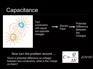
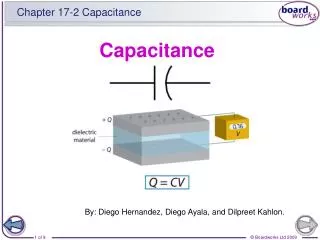
Chapter 6. Dielectrics and Capacitance. Capacitance. Now let us consider two conductors embedded in a homogenous dielectric. Conductor M 2 carries a total positive charge Q , and M 1 carries an equal negative charge – Q .

E N D
Chapter 6 Dielectrics and Capacitance Capacitance • Now let us consider two conductors embedded in a homogenous dielectric. • Conductor M2 carries a total positive charge Q, and M1carries an equal negative charge –Q. • No other charges present the total charge of the system is zero. • The charge is carried on the surface as a surface charge density. • The electric field is normal to the conductor surface. • Each conductor is an equipotential surface
Chapter 6 Dielectrics and Capacitance Capacitance • The electric flux is directed from M2 to M1, thus M2 is at the more positive potential. • Works must be done to carry a positive charge from M1 to M2. • Let us assign V0 as the potential difference between M2 and M1. • We may now define the capacitance of this two-conductor system as the ratio of the magnitude of the total charge on either conductor to the magnitude of the potential difference between the conductors.
Chapter 6 Dielectrics and Capacitance Capacitance • The capacitance is independent of the potential and total charge for their ratio is constant. • If the charge density is increased by a factor, Gauss's law indicates that the electric flux density or electric field intensity also increases by the same factor, as does the potential difference. • Capacitance is a function only of the physical dimensions of the system of conductors and of the permittivity of the homogenous dielectric. • Capacitance is measured in farads (F), 1 F = 1 C/V.
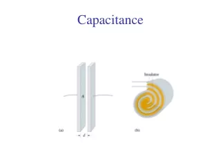
Chapter 6 Dielectrics and Capacitance Capacitance • We will now apply the definition of capacitance to a simple two-conductor system, where the conductors are identical, infinite parallel planes, and separated a distance d to each other. • The charge on the lower plane is positive, since D is upward. • The charge on the upper plane is negative,
Chapter 6 Dielectrics and Capacitance Capacitance • The potential difference between lower and upper planes is: • The total charge for an area S of either plane, both with linear dimensions much greater than their separation d, is: • The capacitance of a portion of the infinite-plane arrangement, far from the edges, is:
Chapter 6 Dielectrics and Capacitance Capacitance • Example • Calculate the capacitance of a parallel-plate capacitor having a mica dielectric, εr = 6, a plate area of 10 in2, and a separation of 0.01 in.
Chapter 6 Dielectrics and Capacitance Capacitance • The total energy stored in the capacitor is:
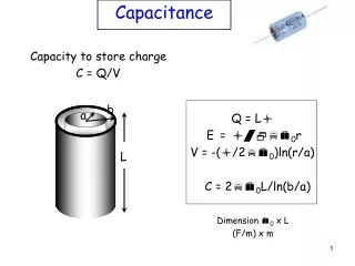
Chapter 6 Dielectrics and Capacitance Several Capacitance Examples • As first example, consider a coaxial cable or coaxial capacitor of inner radius a, outer radius b, and length L. • The capacitance is given by: • Next, consider a spherical capacitor formed of two concentric spherical conducting shells of radius a and b, b>a.
Chapter 6 Dielectrics and Capacitance Several Capacitance Examples • If we allow the outer sphere to become infinitely large, we obtain the capacitance of an isolated spherical conductor: • A sphere about the size of a marble, with a diameter of 1 cm, will have: • Coating this sphere with a different dielectric layer, for which ε = ε1, extending from r = a to r = r1,
Chapter 6 Dielectrics and Capacitance Several Capacitance Examples • While the potential difference is: • Therefore,
Chapter 6 Dielectrics and Capacitance Several Capacitance Examples • A capacitor can be made up of several dielectrics. • Consider a parallel-plate capacitor of area S and spacing d, d << linear dimension of S. • The capacitance is ε1S/d, using a dielectric of permittivity ε1. • Now, let us replace a part of this dielectric by another of permittivity ε2, placing the boundary between the two dielectrics parallel to the plates. • Assuming a charge Q on one plate, ρS = Q/S, while DN1 = DN2, since D is only normal to the boundary. • E1 = D1/ε1 = Q/(ε1S),E2 = D2/ε2 = Q/(ε2S). • V1 = E1d1, V2 = E2d2.
Chapter 6 Dielectrics and Capacitance Several Capacitance Examples • Another configuration is when the dielectric boundary were placed normal to the two conducting plates and the dielectrics occupied areas of S1 and S2. • Assuming a charge Q on one plate, Q = ρS1S1 + ρS2S2. • ρS1 = D1 = ε1E1,ρS2 = D2 = ε2E2. • V0 = E1d = E2d.
Chapter 6 Dielectrics and Capacitance Capacitance of a Two-Wire Line • The configuration of the two-wire line consists of two parallel conducting cylinders, each of circular cross section. • We shall be able to find complete information about the electric field intensity, the potential field, the surface charge density distribution, and the capacitance. • This arrangement is an important type of transmission line. • Schematics of a transmission line
Chapter 6 Dielectrics and Capacitance Capacitance of a Two-Wire Line • The capacitance, together with conductance, forms a shunt admittance of a transmission line. • The line capacitance is proportional to the length of the transmission line. • When an alternating voltage is applied to the line, the line capacitance draws a leading sinusoidal current, called the charging current. • The charging current is negligible for lines less than 100 km long. For longer lines, the capacitance becomes increasingly important and has to be accounted for. • The value of such capacitance is significantly higher with underground cables than with overhead lines, due to the close proximity of the individual conductors.
Chapter 6 Dielectrics and Capacitance Capacitance of a Two-Wire Line • The potential field of two infinite line charges, with a positive line charge in the xz plane at x = a and a negative line at x = –a, is shown below. • The potential of a single line charge with zero reference at a radius of R0 is: • The combined potential field can be written as:
Chapter 6 Dielectrics and Capacitance Capacitance of a Two-Wire Line • We choose R10 = R20, thus placing the zero reference at equal distances from each line. • Expressing R1 and R2 in terms of x and y, • To recognize the equipotential surfaces, some algebraic manipulations are necessary. • Choosing an equipotential surface V = V1, we define a dimensionless parameter K1 as: so that
Chapter 6 Dielectrics and Capacitance Capacitance of a Two-Wire Line • After some multiplications and algebra, we obtain: • The last equation shows that the V = V1equipotential surface is independent of z and intersects the xyplane in a circle of radius b, • The center of the circle is x = h, y = 0, where:
Chapter 6 Dielectrics and Capacitance Capacitance of a Two-Wire Line • Let us now consider a zero-potential conducting plane located at x = 0, and a conducting cylinder of radius b and potential V0 with its axis located a distance h from the plane. • Solving the last two equations for a and K1 in terms of b and h, • The potential of the cylinder is V0, so that: • Therefore,
Chapter 6 Dielectrics and Capacitance Capacitance of a Two-Wire Line • Given h, b, and V0, we may determine a, K1, and ρL. • The capacitance between the cylinder and the plane is now available. For a length L in the z direction, • Prove the equity by solving quadratic equation in eα, where cosh(α)=h/b. • cosh(α) = (eα+e–α)/2
Chapter 6 Dielectrics and Capacitance Capacitance of a Two-Wire Line • Example • The black circle shows the cross section of a cylinder of 5 m radius at a potential of 100 V in free space. Its axis is 13 m away from a plane at zero potential.
Chapter 6 Dielectrics and Capacitance Capacitance of a Two-Wire Line • We may also identify the cylinder representing the 50 V equipotential surface by finding new values for K1, b, and h.
Chapter 6 Dielectrics and Capacitance Capacitance of a Two-Wire Line
Chapter 6 Dielectrics and Capacitance - - - - - - - - + + + + + + + + Capacitance of a Two-Wire Line
Chapter 6 Dielectrics and Capacitance Capacitance of a Two-Wire Line • For the case of a conductor with b << h, then:
Chapter 6 Dielectrics and Capacitance Homework 8 • D6.4. • D6.5. • D6.6. • All homework problems from Hayt and Buck, 7th Edition. • Due: Monday, 17 June 2013.