Download
1 / 23
230 likes | 393 Views
Tests of Fast Timing Detectors in the Fermilab Test Beam, etc. (T979) MTest : May 27 th – June 2 nd. Mike Albrow, Sasha Pronko, Erik Ramberg, Anatoly Ronzhin, Andriy Zatserklyaniy + detector simulations by Hans Wenzel & Earle Wilson (student). Motivations for ~ ps / 10 ps timing detectors

E N D
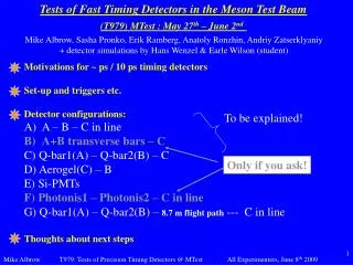
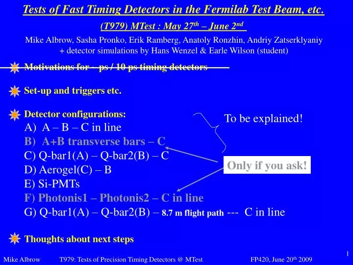
Tests of Fast Timing Detectors in the Fermilab Test Beam, etc. (T979)MTest : May 27th – June 2nd Mike Albrow, Sasha Pronko, Erik Ramberg, Anatoly Ronzhin, Andriy Zatserklyaniy + detector simulations by Hans Wenzel & Earle Wilson (student) • Motivations for ~ ps / 10 ps timing detectors • Set-up and triggers etc. • Detector configurations: • A – B – C in line • A+B transverse bars – C • C) Q-bar1(A) – Q-bar2(B) – C • D) Aerogel(C) – B • E) Si-PMTs • F) Photonis1 – Photonis2 – C in line • G) Q-bar1(A) – Q-bar2(B) – 8.7 m flight path --- C in line • Thoughts about next steps To be explained! Only if you ask!
hep-ex/0511057 A&R: hep-ph/0009336:
Pile-up reduction in FP420 Want L ~ 10^34, <n> ~ 25/x ? z(vertex) from pp == z(vertex) central cf σ(z)vtx ~ 50 mm to CMS Exec Board Summer 2008 (ATLAS also reviewing)
At MTest, 120 GeV/c p, ~40,000/spill / 1 spill per minute Simple trigger (schematic): 2mm x 2mm scint. VETO w/hole 2 PMTs in AND 2 PMTs in OR First A-B-C in line Dark & shielded box 210 C A B PHOTEK 210 2 MCP, 10mm Φ PHOTEK 240 2 MCP, 40mm Φ Calibrate electronics resolution with same pulse start & stop: σ= 4.0 ps Cerenkov light in Quartz windows (~5mm, 9mm). HV ~ 4.5 kV, G ~ 5.10^5 Schematic DAQ : ADC DAQ MCP- PMT-A ORTEC 566, 567 TAC/SCA T1 ORTEC AD114 ADC ATTENUATOR MCP- PMT-B ATTENUATOR ADC
A-B-C in-line results: Cerenkov light in PMT windows All numbers “preliminary”, to be double-checked ADC distributions: cut out tails and stragglers (~ 10%) T1 = tA – tB T2 = tA – tC T3 = tB – tC ======= Check Ti(PH A,B) Make slewing corrections Unfold: A B C etc. PMT-1 (Photek-210, 4.7 kV)=10.8 psPMT-2 (Photek-210, 4.6 kV)=11.5 psPMT-3 (Photek-240, 4.2 kV)=5.1 ps Cerenkov light in PMT windows 9.4 mm, 5.5 mm +/- ~ 0.2 ps
Double Q-bar Quartz (fused silica) bars 6mm x 6mm x 90mm PHOTEK 210 Mounted at Cherenkov angle θc ~ 48 deg. on opposite sides. dz = 6 mm/sin(48) = 8.1 mm. Some light direct to PMT, ~1/2 TIR to PMT Black “sock” over bars just to avoid light sharing Unfold: σ(A) = 22.3 ps σ(B) = 30.5 ps B Includes electronics (~3 ps) and 2 mm beam width smear (A,B) Δt = 2 mm x (10 ps/2 mm) C A Difference? Optical coupling? Combining [AB] removes beam spread (later, tracking)
Resolution of Double-Qbar as one device T1 = A - BT2 = A - CT3 = B - C ------------T1 + T2 = A - B + A - C3 x T3 = 3B - 3Cso T1 + T2 + 3x T3 = A - B + A - C + 3B - 3C = 2A + 2B - 4Cand 1/4 ( T1 + T2 + 3x T3 ) = (A+B)/2 - C σ = 6.04 ch = 18.7 ps Unfold C = 7.7 ps, σ(AB) = 17.0 ps Resolution of double-Q-bar 2 mm x-spread not to be subtracted (only 3 ps electronics)
Switched on, saw signals! A = Aerogel B Corrected T2 = A-B = 10.8 ch = 33.5 ps (before unfolding)
Aerogel results: Unfolding indirect because only 2 PMTs in run. A (Aerogel on 240) and B(210 in beam) T1 = t(A) – t(B) corrected for smearing: 10 mm aero σ(T1) = 43.7 ps 20 mm aero σ(T1) = 45.3 ps 30 mm aero σ(T1) = 33.5 ps <P.H.> = 46 ch. (10mm) 72 ch. (30 mm) Unfold with σ(1) = 12 ps from in-line σ (Aerogel 30 mm) ~ 31 ps Aerogel + mirror ~ massless & short (~ 5 cm), simple. Could have several in line, independent √N BUT: have large 240 tube close to beam Possibilities to focus light : smaller tube farther away, to be simulated MCP-PMT AEROGEL
A focusing Aerogel Counter Normally Cerenkov light can only be focused to a ring. But if beam is very small (needle beam) you can focus to a point. Smaller PMT and farther from beam. MCP-PMT : all light simulltaneous (from all z! isochronous) e.g. f (can be far-ish) p (needle beam) off-axis parabolic mirror conical lens (quartz) Question is: if needle 6mm x 6mm? Image size? 40mm MCP?
Tests of SiPMs = silicon photomultipliers Eight Hamamatsu SiPMs, 3mm x 3mm In beam with quartz Cherenkov radiators several thicknesses (4 – 12mm), mirrored and not mirrored. Best conditions σ(t) ~ 33 – 37 ps 10-15 photoelectrons Channels Between SiPMs and C. Slewing correction applied SiPM on end of bars?
World’s Best Beamline Time-of-Flight System? Start = Double-Q-bar Stop = Photek 240 Start-stop dist. = 8.7 m Predictions of proton positions 24 psec resolution positron peak, Using average of A & B times Can measure momentum of a proton with 2 MCP-PMTs! (if you know it’s a proton!)
Possible Next Steps For FP420 a σ(t) = 10 ps edgeless detector we learnt a way Need to include CMS-compatible electronics/DAQ with reference time signals (jitter <~ 5 ps) Should get < ~ 8 ps θc = 48deg Q-bars onto PHOTEK 240 MCP-PMTs 20mm 6mm x 6mm bars TIR: isolated MCP I “beam” only 6mm vert., 20 mm horiz. MCP 40 mm diam. MCP p + More aerogel? To test in Fall?
Design by John Rauch & Carl Lindenmeyer 5 x 3 QUARTIC Protons go through 5 6mm bars (inclined so ~ 8.4 mm) 3 bars wide ~ 20 mm 40 mm Φ pmt Why better than old QUARTICs? Better, single channel 40mm MCP All light isochronous (1st idea) Bars touch nothing on sides (precision boxes) Pressure on PMT with optical grease
Needs work!! But CAD GEANT4 presumably and CMSSW Ensemble QUARTICs : two 5-6 bars in line, UP & DOWN Inter-bar gaps not in line: Some particles in only one (good) UP & DOWN good for checking resolution, independent of y Two single bars out to side, one covers full 8mm x 24mm and (maybe) one retracted to cover 8mm x outer 20 mm (e.g.) John Rauch, sent yesterday!
Earle Wilson (student) and Hans Wenzel doing some GEANT4 simulations of QUARTIC. First results (not checked) Photoelectrons: Hamamatsu MCP-PMT R3809U-65 Photoelectrons: Photek 240
Timing and Timing-Resolution vs. Angle Incident Beam Earle Wilson (student) and Hans Wenzel Photoelectrons: Hamamatsu MCP-PMT R3809U-65 Photoelectrons: Hamamatsu MCP-PMT R3809U-65 Photoelectrons: Photek 240 Photoelectrons: Photek 240 -Timing and timing resolution obtained using DCOG Method -Cerenkov Angle: 48.2 -Jitter: 30 psec -Gain: 100 -Each data point is taken over 1000 events. I’m not sure about abs values, but 48deg gets light fastest, but more acute angle more p.e. and better time resolution. Unfortunately did not test this!
Reference timing. We are continually asked for a practical demo. OK yes we should! Nobody else has volunteered; I hope a FNAL-LLNL combined effort can do this. I will focus a bit more on it! Brian Chase is our best Fermilab person, he presented something to us in Feb: From his slides:
Possible future development: GHz streak camera (concept only): In principle, timing up to several protons/bunch crossing. MCP (if needed) low gain. All in vacuum tube of course: Use precision space for precision time Cerenkov photons RF sweep (both x and y) ~ 10 kV acceleration tube ~ 400 MHz RF 4 x 400 = 1.2 GHz = 830 ps period CMS Pixel detector, 25ns readout Window & photocathode MCP(maybe) Focusing triplet Magnetostatic or Electrostatic MGA + Vic Scarpine (FNAL) interested and expert … so far just thinking. Hope for full simulation. Say ~ 10 p.e. MCP gain ~ 100 (?) 1000 e’s in beam At focusing lens ~ 1000 x 10 keV electrons. Good signal in pixel detector. Time spread ~ r/L can be kept to < 5 ps (L ~ 20 cm) Say sweep circle r = 10 mm, 830 ps, 100 μm pixels 1.5 ps/pixel. Depending on aberrations etc, maybe measure >= 2 times if dt >~ 20 ps.
Summary (IMO): We have (at least) THREE promising phase 1 detectors: GASTOF --- QUARTIC’ --- Aerogel (if focused) different characteristics: G – 1 channel, Q = multichannel, A = thin & short I think actual < 10 ps detectors will be demonstrated this Fall (Oct?) Electronics is another issue, want σ[detector+electronics] <~ 10 ps (Actually ~ 15-20 may be acceptable initially : future upgrades but we really want future upgrades to be 6 ps, 4 ps, 2 ps! Reference timing is another issue to be demonstrated. Want it to give negligible contribution so σ <~ 5 ps. Will anyone else take it up? Unknown: Stability of system. day-to-day variations can be calibrated out, probably hour-to-hour, but not minute-to-minute.
Back-Up Motivations
Motivations: Timing on single particles σ(t) typically >~ 100 ps A factor 10 – 100 improvement likely to have unforeseen benefits. We know of some (foreseen), e.g.: 2 1 Particle ID in large detectors (~CDF-like or ILC) E.g. at 6 GeV/c, over 1.5m: Δt(π-K) = 17 ps Δt(K-p) = 43 ps ================== Areas ~several m2, want thin. Argonne-Chicago- (Henry Frisch et al.) Fermilab group Particle ID in beams E.g. at 25 GeV/c, over 15m: Δt(π-K) = 20 ps Δt(K-p) = 50 ps or at 10 GeV/c, over 30m: Δt(π-e) = 10 ps ================== Areas ~few cm2, want thin. 3 Pile-up reduction e.g. in FP420: Extensions to CMS & ATLAS in prepn. p + p p + H + p + nothing else Measure p’s M(H), J, C, P, Γ 4 • PET-TOF • β+e Δt = 10ps : Δz = 3mm 240m … 420m CMS H 240m … 420m p p