Download

1 / 12
120 likes | 230 Views
Sand Sampling Apparatus. Eglin Air Force Base Gina Teofilak Richard Klimas Dan Mortensen Ruben De Sousa. Sand Fracture Mechanisms During High-Speed Sand Impacts. William “Bill” Cooper, MSgt Wes Schuler, LT Brad Breaux, Lalit Chhabildas AFRL/RW Munitions Directorate

E N D
Sand Sampling Apparatus Eglin Air Force Base Gina Teofilak Richard Klimas Dan Mortensen Ruben De Sousa
Sand Fracture Mechanisms DuringHigh-Speed Sand Impacts William “Bill” Cooper, MSgt Wes Schuler, LT Brad Breaux, Lalit Chhabildas AFRL/RW Munitions Directorate Air Force Research Laboratory Phil Metzger Granular Mechanics & Surface Systems Lab NASA, Kennedy Space Center Victor Giurgiutiu Air Force Office of Scientific Research 2
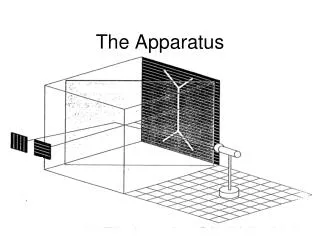
Overview- The Experiment • Target filled with 3000 lbs. sand • Projectile shot through the target • Documentation of virgin & impacted sand grain morphology
Introduction introduction Projectile Fractured sand Target shot line 4
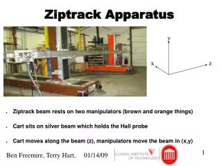
Y X • Current Design Z • Driven by a chain • Steel rod with supports (x-axis) • Actuators with threaded rods (y & z axes) • 3 motors automated • Control system 5
Current Design Cont’d. Eglin Visit 10/31/2008 6
Fabrication • CNC to fabricate end plates and bearing holders • Mill to construct side plates and lead screw nut • Lathe to turn down lead screws and support rods 7
Actuators - Y and Z actuators same concept, but different sizes - Same spacing between stabilizer rods and lead screw - Y actuator is 24in x 8in - Z actuator is 17in x 8in • Z actuator mounted vertically onto the horizontally mounted y actuator • Bearing holders and lead screw nut were precisely fabricated to prevent binding and torque forces 8
Remaining Fabrication • Two 8ft rails with supports every 1ft (x axis) • Various parts that attach the y actuator to x axis: • clamp for the chain • end supports that will house the pulleys for the chain • Group will be going down to Clearwater this weekend to fabricate these parts, and create a base to mount the apparatus for experimentation 9
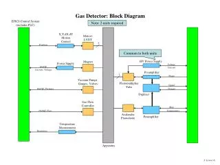
Electronics- Old Method X Direction Movement Motor Controller – Servo Controller Encoder Motor Z Direction Movement Motor Controller – Servo Controller Wall Socket Power Supply Microprocessor Encoder Motor Y Direction Movement Encoder Motor Controller – Servo Controller Motor • Using encoders and servo controllers to do motion control • Became expensive - >$200 per motor 10
X Direction Movement Switches Motor Controller Motor Z Direction Movement Wall Socket Power Supply Microprocessor Switches Motor Controller Motor Y Direction Movement Switches Motor Controller Motor Electronics- New Method • Using switches and hard coding to get motion control desired. • Cheaper but more time consuming. Cabling ran close to the mechanism in twisted pairs and attached away from moving parts. Electronics are being enclosed in a plastic enclosure for protection from the environments. 11
REFERENCES • Cooper, William “Bill”, MSgt Wes Schuler, AFRL/RW • Munitions Directorate • Air Force Research Laboratory • Mortensen, Charles, Owner, Dynatech Associates • Dr. Chiang Shih, FAMU-FSU College of Engineering, Mechanical • Dr. Daudi Waryoba, FAMU-FSU College of Engineering, Mechanical 12