Download
1 / 17
180 likes | 643 Views
DMX512 Programmable Theater Lighting Controller. Jeff Sand and Kris Kopel Advisor: Dr. Don Schertz. Outline. Overall Project Description Digital Theatrical Lighting Control System Block Diagram Functional Description Software Equipment List Project Timeline.

E N D
DMX512 Programmable Theater Lighting Controller Jeff Sand and Kris Kopel Advisor: Dr. Don Schertz
Outline • Overall Project Description • Digital Theatrical Lighting Control • System Block Diagram • Functional Description • Software • Equipment List • Project Timeline
Overall Project Description • PC-Based Theatrical Lighting Console • Windows/Linux PC for User Interface, programming, and status • Several sets of faders and buttons connected via microcontroller • USB Interface between PC and microcontroller
Lights Dimmers Lights Lights Dimmers Lights Lights Dimmers Lights Digital Theatrical Lighting Console DMX512
DMX512 Protocol • Controls up to 512 dimmers/devices • Serial and asynchronous • 250 kbits/s • RS-485 physical implementation • 32 nodes on one chain
Lights Dimmers Lights Lights Dimmers Lights Lights Dimmers Lights Digital Theatrical Lighting Console DMX512
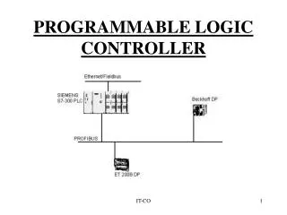
Personal Computer Input Blocks DMX512 Output System Block Diagram Motorola 68376 mController USB! RS485 Driver
Motorola 68376 Microcontroller • Moves data between physical inputs/outputs and the PC • UART for DMX512 output • Queued Serial Module for analog fader and pushbutton inputs • USB Interface to PC
USB Transceiver Control Lines USB QSPI Serial In UART Out RS485 Driver DMX512 Output Microcontroller Block Diagram Motorola 68376 mController
Input Blocks • Modular input blocks • Connected to 68376 using QSM • Standard input blocks: 8 faders, 8 buttons • Master input block: master level fader and submaster faders • Able to define new input block types for later use using software updates
Control Lines Control Logic Serial A/D Out to mController QSPI Module 8 to 1 Mux Input Blocks Fader Inputs Button Inputs
The PC Interface • Provides GUI user interface • Provides scene programming capabilities for the lighting designer • USB interface to external hardware Personal Computer Input from User Interface USB Output to monitor
Software • USB driver development • Direct fader control • Software dimmer “patching” • Programmed lighting queues
Equipment • Windows NT PC for 68376 development (Microtek XRAY package) • Linux/Windows 98 PC for main USB and user software development • Motorola 68376 Development board
Project Status • 68376 Development interface • QSPI, RS-485, USB chip selection • Linux/Windows 98 PC setup • Web site - http://cegt201.bradley.edu/projects/proj2001/pcusbdmx/
Hardware Timeline Week 1: Build header connectors for microcontroller bus and begin work on temporary PC/microcontroller interface Week 2: Develop temporary PC interface Week 3: Finish temporary interface, start DMX output block Week 4: Finish and test DMX output block Week 5: Begin USB interface, input blocks Week 6: Continue USB interface Week 7: Finish input blocks Week 8: Finish USB, begin testing Week 9: Test inputs blocks Week 10: Test/verify DMX output stream Week 11: Miscellaneous hardware testing Week 12/13: Add extra features if time permits
Software Timeline Week 1: Develop interface software for temporary PC/microcontroller interface Week 2: Begin USB drivers Week 3: Write initial DMX512 program for 376 Week 4: Finish and test temporary x86/376 output software Week 5, 6, 7: Continue USB driver software, begin user software Week 8: Start testing USB software on x86 and 376 Week 9: Test input block communication Week 10, 11: Continue and test user software Week 12, 13: Add additional programming and user interface features as time permits