Download
1 / 127
1.28k likes | 1.4k Views
CIS 185 CCNP ROUTE Ch. 7 Implementing Routing Facilities for Branch Offices and Mobile Workers. Rick Graziani Cabrillo College graziani@cabrillo.edu Last Updated: Fall 2010. Materials. Book:

E N D
CIS 185 CCNP ROUTECh. 7 Implementing Routing Facilities for Branch Offices and Mobile Workers Rick Graziani Cabrillo College graziani@cabrillo.edu Last Updated: Fall 2010
Materials • Book: • Implementing Cisco IP Routing (ROUTE) Foundation Learning Guide: Foundation learning for the ROUTE 642-902 Exam • By Diane Teare • Book • ISBN-10: 1-58705-882-0 • ISBN-13: 978-1-58705-882-0 • eBook • ISBN-10: 0-13-255033-4 • ISBN-13: 978-0-13-255033-8
At the end of this presentation… • Created our broadband connection • Configured a floating static route • If Private WAN is down use Internet (ISP) • Configured NAT for traffic over Internet • Changes private source IP address for traffic over the Internet • Configured IPsec • Want all traffic including LAN-to-LAN to use Internet (ISP) • Want to secure LAN-to-LAN traffic between Branch and HQ over the Internet using IPsec • Problem: LAN-to-LAN traffic is being sent over Private WAN • Solution: Modify NAT to create a NAT exemption • Problem: IPsec does not support broadcasts and multicasts so cannot send EIGRP routing updates • Solution: Use GRE tunnel – Encapsulate traffic inside a GRE point-to-point tunnel, then inside an IPsec tunnel • Must add GRE tunnel network to EIGRP so all LAN-to-LAN traffic uses GRE tunnel
Branch Office Requirements • There are common requirements that every branch network design needs to address: • Connectivity • Security • Availability • Voice • Application
The challenges when addressing these requirements include the following: • Bandwidth and network requirements • Video, voice, and data, and supporting mission critical functions and applications. • Consolidated data centers • Centralized security and management control • Mobility • The dispersion of the staff coupled with the consolidation of the IT resources • Disparate networks • Branch offices built in isolation running aging and separate voice and data networks. • Management costs • Patchwork of network devices in which branch offices often have very different equipment and architectures.
Upgrade Scenario • HQ router routes to the branches using EIGRP as routing protocol • Currently no redundancy • The branch site also provides basic services: • DHCP • NAT
When deploying branch services, one must consider how the following trends and considerations affect the implementation plan: • Consolidation • Integration • High availability • VPNs as a WAN option
Implementation Plan • To accomplish the branch office upgrade we will include configurations at both the branch and the headquarters routers, as follows: Step 1 Deploy broadband connectivity Step 2 Configure static routing Step 3 Document and verify other services Step 4 Implement and tune the IPsec VPN Step 5 Configure GRE tunnels
Step 1: Deploying Broadband Connectivity • Broadband technologies provide always on access which can support enhanced voice and video services. • Often refers to any connection of 256 Kbps or greater.
Broadband (FYI) • Broadband: • (General) Data transmission using multiplexing methodology to provide more efficient use of the bandwidth. • (Cable) Frequency Division Multiplexing (FDM) of multiple signals in a wide radio frequency (RF) bandwidth over hybrid fiber-coaxial (HFC) network and the capability to handle large amounts of information. • Frequency Division Multiplexing: FDM is a means by which information from multiple channels or frequencies can be allocated bandwidth on a single wire.
Broadband can include many different connection options, including: • Wireless broadband • Broadband cable access • Digital subscriber line (DSL)
Wireless Broadband • New developments in broadband wireless technology include: • Municipal Wi-Fi • WiMAX • Satellite Internet
Municipal Wi-Fi • Uses a mesh (series) of access points (radio transmitters). • Each access point can communicate with at least two other access points. • Signals travel from access point to access point through this cloud until: • Reach a node that has a wired connection to the Internet. • Reach a backhaul node
WiMAX (Worldwide Interoperability for Microwave Access) - IEEE 802.16 • Provides wireless data over long distances • Advantages over WiFi, WiMAX operates: • At higher speeds • Over greater distances • For a greater number of users than Wi-Fi • A WiMAX tower station connects directly to the Internet using a high-bandwidth connection (ex: T3 line or mircrowave). • WiMAX is able to provide coverage to rural areas out of reach of "last mile" cable and DSL technologies.
FYI: http://www.wimax.com/general/what-is-wimax • WiMAX is a wireless digital communications system, also known as IEEE 802.16, that is intended for wireless "metropolitan area networks". • WiMAX can provide broadband wireless access (BWA) up to 30 miles (50 km) for fixed stations, and 3 - 10 miles (5 - 15 km) for mobile stations. • In contrast, the WiFi/802.11 wireless local area network standard is limited in most cases to only 100 - 300 feet (30 - 100m).
Satellite • There are three ways to connect to the Internet using satellites: • One-way multicast satellite • Most IP protocols require two-way communication (web pages) • Full interactivity is not possible.
One-way terrestrial return satellite • Traditional dialup access to send outbound data through a modem • Receive downloads from the satellite
Two-way satellite • Satellites are used for sending and receiving data
Cable Background Information • Not popular for connecting branch sites • Many businesses do not have access to cable because cable TV’s main customers are residential neighborhoods. • Uses a coaxial cable that carries radio frequency (RF) signals across the network. • Primary medium used to build cable TV systems.
Hybrid Fiber-Coaxial Networks (FYI) Transportation Network • HFC architecture is relatively simple. • A web of fiber trunk cables connects the headend (or hub) to the nodes where optical-to-RF signal conversion takes place. • The fiber carries the same broadband content as coax for: • Internet connections • telephone service • streaming video
Hybrid Fiber-Coaxial Networks (FYI) Transportation Network • Coaxial feeder cables originate from the node that carries RF signals to the subscribers. • The effective range or service area of a distribution network segment (feeder segment) is from 100 to as many as 2000 subscribers.
Putting it all together (FYI) RF RF • Step 1 • In the downstream path, the local headend (LHE) receives television signals through the satellite dishes, antennas, analog and digital video servers, local programming and other headends. • The CMTS (cable modem termination system) modulates digital data on an RF signal and combines that RF signal with the TV signals.
Putting it all together (FYI) light • Step 2 • The combined signal is input to a fiber transmitter that converts the signal from RF to light (optical) and transmits to a fiber node further downstream. • The Fiber Node is located relatively close to the subscribers.
Putting it all together (FYI) RF • Step 3 • The Fiber Node coverts the light back to RF. • RF transmitted over the coaxial network comprised of: • amplifiers • Taps • drops.
Putting it all together (FYI) • Step 4 • At the subscriber end: • RF splitterdivides the combined RF signal into video and data • Cable Modem receives the data portion of the RF signal. • Tuned to the data RF signal channels, demodulates the data RF signal back into digital data and finally passes the data to the computer over an Ethernet or 802.11a/b/g connection. • Cable set-top box receives the video portion of the RF signal.
Putting it all together (FYI) • Outbound or Upstream Direction • CM decodes the digital information from the Ethernet connection, modulates a separate RF signal with this digital information. • CM transmits this signal at a certain RF power level. • At the headend, the CMTS, tuned to the data RF channels, demodulates the data RF signal back to digital data and routes the digital data to the Internet.
DSL Background Information • Several years ago, research by Bell Labs identified that a typical voice conversation over a local loop only required the use of bandwidth of 300 Hz to 3400 Hz. • This was enough of a frequency range for normal voice conversation – low to high. • For many years, the telephone networks did not use the bandwidth beyond 4 kHz.
DSL • DSL types fall into two major categories, taking into account downstream and upstream speeds: • Symmetrical DSL: Upstream and downstream speeds are the same. • Asymmetrical DSL: Upstream and downstream speeds are different. Downstream speed is typically higher than upstream speed. • Term xDSL covers a number of DSL variations. • Data rate that DSL service can provide depends on the distance between the subscriber and the CO. • The shorter the distance: the higher the bandwidth available.
Data Transmission over ADSL • Three ways to encapsulate IP packets over DSL connection: • RFC 1483/2684 Bridged • PPP over Ethernet (PPPoE) • PPP over ATM (PPPoA)
PPP over ATM (PPPoA) • PPPoA used mainly with cable modem, DSL and ADSL services • Provides: • Authentication • Encryption • Compression • Slightly more overhead than PPPoE • PPPoA is a routed solution, unlike RFC 1483 Bridged and PPPoE.
Configuring PPPoA • In our scenario, the Internet service provider has provided the branch site with a PPPoA connection to the Internet. • The steps to configure PPPoA on the branch router, where components of both the DSL architecture and of basic branch IP services are required, are as follows: 1. Configure an ATM interface. 2. Configure a dialer interface. 3. Configure PAT. 4. Configure the branch router as a local DHCP server. 5. Configure a static default route.
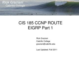
CPE ATM IP PVC DHCPServer ISPRouter E0/0 ATM0/0 • ATM and dialer interfaces will establish the ATM virtual circuits and the PPP sessions. • A dialer interface is a virtual interface that is configured as an on-demand component. • Up upon successful DSL subscriber authentication.
This presentation… • Created our broadband connection • Configured a floating static route • If Private WAN is down use Internet (ISP) • Configured NAT for traffic over Internet • Changes private source IP address for traffic over the Internet • Configured IPsec • Want all traffic including LAN-to-LAN to use Internet (ISP) • Want to secure LAN-to-LAN traffic between Branch and HQ over the Internet using IPsec • Problem: LAN-to-LAN traffic is being sent over Private WAN • Solution: Modify NAT to create a NAT exemption • Problem: IPsec does not support broadcasts and multicasts so cannot send EIGRP routing updates • Solution: Use GRE tunnel – Encapsulate traffic inside a GRE point-to-point tunnel, then inside an IPsec tunnel • Must add GRE tunnel network to EIGRP so all LAN-to-LAN traffic uses GRE tunnel
Here is a high-level overview of the Branch Router configuration
The branch router provides DHCP services to users connected to the inside LAN interface. • Users connecting to the inside LAN interface would be provided with a private address from the 192.168.1.0 pool.
The configuration specifics of the ATM 0/0 interface and the permanent virtual circuit (PVC) are provided by the DSL service provider. • Notice the combination of the ATM interface dialer pool-member 1 command and the dialer interface dialer-pool 1 commands. • These two commands associate the ATM 0/0 interface to the Dialer 0 interface.
The Dialer 0 interface is a virtual interface that initiates PPP connectivity including authentication • Notice that it is also identified as the outside NAT interface.
NAT is configured to translate traffic initiated at the LAN port to the IP address of the dialer interface, which is obtained via DHCP from the DSL provider.
Notice that the static default route points to the dialer interface. • The routing of traffic to this default route would trigger the dialer interface to activate.
This presentation… • Created our broadband connection • Configured a floating static route • If Private WAN is down use Internet (ISP) • Configured NAT for traffic over Internet • Changes private source IP address for traffic over the Internet • Configured IPsec • Want all traffic including LAN-to-LAN to use Internet (ISP) • Want to secure LAN-to-LAN traffic between Branch and HQ over the Internet using IPsec • Problem: LAN-to-LAN traffic is being sent over Private WAN • Solution: Modify NAT to create a NAT exemption • Problem: IPsec does not support broadcasts and multicasts so cannot send EIGRP routing updates • Solution: Use GRE tunnel – Encapsulate traffic inside a GRE point-to-point tunnel, then inside an IPsec tunnel • Must add GRE tunnel network to EIGRP so all LAN-to-LAN traffic uses GRE tunnel
Configuring Routing and Floating Static Route • Because PPP, ATM and DSL are beyond the scope of this chapter we will modify our scenario without DSL.
EIGRP • Currently, the main connection to the HQ is via the private WAN network because it is configured for routing with EIGRP.
Default • What happens if the private WAN link fails? • Traffic to the HQ e-mail server or to the Internet would not be possible. • By adding floating default static route to the branch router, we can accomplish resiliency. • Whenever the link through the private WAN link fails, the floating would populate the routing table. • When the private WAN reactivates, EIGRP would reroute traffic through the private WAN.
EIGRP Default • It would seem like this would work but ... • This scenario would really not be feasible, because the private addresses of the branch LAN would be filtered by the ISP router. • Therefore, on the branch router, the internal private IP addresses must be translated via NAT to global public IP addresses.
This presentation… • Created our broadband connection • Configured a floating static route • If Private WAN is down use Internet (ISP) • Configured NAT for traffic over Internet • Changes private source IP address for traffic over the Internet • Configured IPsec • Want all traffic including LAN-to-LAN to use Internet (ISP) • Want to secure LAN-to-LAN traffic between Branch and HQ over the Internet using IPsec • Problem: LAN-to-LAN traffic is being sent over Private WAN • Solution: Modify NAT to create a NAT exemption • Problem: IPsec does not support broadcasts and multicasts so cannot send EIGRP routing updates • Solution: Use GRE tunnel – Encapsulate traffic inside a GRE point-to-point tunnel, then inside an IPsec tunnel • Must add GRE tunnel network to EIGRP so all LAN-to-LAN traffic uses GRE tunnel
Configuring NAT/PAT for Branch Services • Notice the NAT pool of global IP addresses available on the branch router. • Also notice that the Branch server has a static NAT global address (209.165.200.254). • The branch router must be configured to deploy NAT as shown above. • There are three generic steps to configuring NAT. • Which traffic will be translated • To what address will it be translated • Which interfaces are involved in the translation selection
Configure the interfaces involved in this particular NAT translation (outside interface is ISP facing interface) • Translate addresses coming from the branch LAN, regardless of destination. • The NAT pool of public IP address is defined using the ip nat pool command. • The NAT pool is named BRANCH-NAT-POOL and identifies a range of valid and available Internet IP address. • ip nat inside source command: “From BRANCH-NAT-ACL to BRANCH-NAT-POOL” • Creates a static translation entry in the router, where the inside local address 192.168.1.254 is always translated to the global 209.165.200.254 on the outside. interface serial 0/0/1 ip nat outside interface fastethernet 0/0 ip nat inside ip access-list extended BRANCH-NAT-ACL permit ip 192.168.1.0 0.0.0.255 any ip nat pool BRANCH-NAT-POOL 209.165.200.249 209.165.200.253 prefix-length 29 ip nat inside source list BRANCH-NAT-ACL pool BRANCH-NAT-POOL ip nat inside source static 192.168.1.254 209.165.200.254


![Cisco CCNP Routing and Switching 300-101 ROUTE Practice Questions [2019 Updated]](https://cdn4.slideserve.com/8134463/ccna-300-101-dt.jpg)