Download
1 / 29
290 likes | 422 Views
Monoenergetic Proton Beams from Laser Driven Shocks. Dan Haberberger Neptune Laboratory, Department of Electrical Engineering, UCLA. In collaboration with: Sergei Tochitsky , Chao Gong, Warren Mori, Chan Joshi Neptune Laboratory, Department of Electrical Engineering, UCLA

E N D
Monoenergetic Proton Beams from Laser Driven Shocks Dan Haberberger Neptune Laboratory, Department of Electrical Engineering, UCLA In collaboration with: Sergei Tochitsky, Chao Gong, Warren Mori, Chan Joshi Neptune Laboratory, Department of Electrical Engineering, UCLA FredericoFiuza, Luis Silva Instituto Superior Technico, Lisbon, Portugal
Outline Applications of Laser Driven Ion Acceleration (LDIA) : Hadron cancer therapy Localized energy deposition : Bragg Peak Therapy centers : conventional accelerators vs. lasers Ion source requirements Collisionless Shock Wave Acceleration (SWA) of protons 1D OSIRIS Simulations Laser driven case UCLA proton acceleration experiment : CO2 laser and a H2 gas jet target Results : Spectra, emittance Interferometry : Plasma density profile 2D OSIRIS simulations Modeling the experiment Scaling to higher power lasers Using 1µm laser systems Conclusion Neptune Laboratory AAC (Jun 2012)
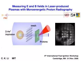
Laser Driven Ion Beam Applications • Probing of strong electric fields in dense plasma on the picosecond timescale • ~1μm resolution, 5-20MeV • Borghesi, Phys. Plasmas (2002) • 50μm Ta wire • Imaging with 6-7MeV protons VULCAN Laser, 20J, 1019W/cm2 -15ps -5ps 5ps • Picosecond injectors for conventional accelerators • 1-10MeV, <.004 mm.mrad, <10-4eV.s [Cowan, Phys. Rev. Lett. (2004)] Markus Roth WG6 : Tuesday 1:30 • Fast Ignition • 15-23MeV • <20ps • Eff = 10% • Hadron Cancer Therapy • 250MeV, 109-1010 protons/s • ΔE/E ≤ 5% Neptune Laboratory AAC (Jun 2012)
Energy Deposition : Ions vs. Photons Bragg Peak for ions results in localized energy deposition Neptune Laboratory AAC (Jun 2012)
Multi-beam Localization Simulations of Irradiating the Human Skull Radiation dose relative to peak (100%) GSI Helmholtz Centre for Heavy Ion Research in Darmstadt http://www.weltderphysik.de/gebiet/leben/tumortherapie/warum-schwerionen/ Neptune Laboratory AAC (Jun 2012)
Problem : Cost and Size • Cost : ~200 Million USD • Accelerator ring (20m) • Transport magnets • Complicated Gantry • Radiation shielding 20 meters 25 meters • Only a few in operation along with ~30 small facilites • 10’s of thousands of people treated • Need more than an order of magnitude more therapy centers Heidelberg Ion-Beam Therapy Center, Commissioned in 2009 http://www.klinikum.uni-heidelberg.de/Welcome.113005.0.html?&L=1 Neptune Laboratory AAC (Jun 2012)
Solution : Laser Based Accelerators Goal Cost : 10-20 million USD Table top laser system (developing) Transportation : Mirrors Only has focusing magnet Gantry : small, protons generated in direction of patient M. Murakami, et al., AIP Conf. Proc. 1024 (2008) 275, doi:10.1063/1.2958203 Neptune Laboratory AAC (Jun 2012)
Proton Beam Requirements Laser Driven Ion Acceleration (LDIA) Radiation Beam Requirements 2 Gray in 1 liter tumor in a few minutes -Translates to 1010 protons per second Proton energies in range of 250 MeV Energy Spread of ~5% Focusability, Energy Accuracy, Energy Variability, Dose Accuracy, etc. Lasers can accelerate up to 1012 protons in a single shot Worlds most powerful lasers have produced 75 MeV protons Vast majority of beams have continuous energy spread Future Work Dose Energy Energy Spread Neptune Laboratory AAC (Jun 2012)
What is a Shock Wave? A disturbance that travels at supersonic speeds through a medium Subsonic Sonic Supersonic • At supersonic speeds, pressure will build at the front of a disturbance forming a shock • Characterized by a rapid change in pressure (density and/or temperature) of the medium In a plasma, a shock wave is characterized by a propagating electric field at speeds useful for ion acceleration (Vsh > 0.01c) Neptune Laboratory AAC (Jun 2012)
1D OSIRIS Simulations In Plasmas, the driver is a potential or electric field Driven Shocks Expansion Shocks • Initial drift causes overlap; overlap causes local density increase and again ambipolar electric field is driven into the plasma • Ambipolar electric field of Plasma 1 is driven into Plasma 2 Plasma 1 ne1 Te Cold Ions Vd /2→ ←Vd /2 Plasma 2 ne2 Te Cold Ions Plasma 1 ne1 = ne2 Te1 Cold Ions Plasma 2 ne1 = ne2 Te1 Cold Ions Neptune Laboratory AAC (Jun 2012)
1D Sims : Driven Shocks (Te = 511 keV Cs = 0.0233c). Wave train response Proton trapping begins Proton reflection begins Strong damping of wave Reflection Condition eɸ > 1/2mv2 No interaction Neptune Laboratory AAC (Jun 2012)
Shock formation in laser driven plasmas Shock acceleration Sheath Field (TNSA) High-intensity laser pulse E • Linearly polarized laser incident upon an overcritical target creates and heats the plasma • Ponderomotive force creates density spike and imparts a velocity drift on surface plasma Beam quality destroyed by TNSA fields Denavit PRL 1992, Silva PRL 2004 Neptune Laboratory AAC (Jun 2012) F. Fiuza | Prague, April 20 | SPIE 2011
CO2 Laser Interacting with a Gas Jet Target CR-39 Nuclear Track Detectors Gas jet target advantages for Shock Wave Acceleration (SWA) Gas plume 120µm 1mm IL = 5x10¹⁶ W/cm2 • Gas jets can be operated at or above 1019 cm-3 (ncr for 10µm) • Long scale length plasma on the back side of the gas jetinhibits strong TNSA fields preserving proton spectrum • High repetition rate source • Clean source of ions (H2, He, N2, O2, Ar, etc…) • Low plasma densities allows for probing of plasma dynamics using visible wavelengths Steepened Plasma Extended Plasma hybrid PIC E TNSA ~ 1/L Interferometry 1ps 532nm Neptune Laboratory AAC (Jun 2012)
CO2 Laser Pulse Temporal Structure Experimentally Measured Temporal Profile Calculated CO2 Gain Spectrum E = 50 J Ppeak = 4TW Pulse Separation = 1/55GHz = 18.5ps 7-10 pulses long Pressure = 8atm Line Separation = 55GHz Line Center : 10.6µm 55GHz 18.5ps 1.2THz ~70ps 3ps D. Haberberger et al., Opt. Exp. 18, 17865 (2010) Neptune Laboratory AAC (Jun 2012)
CR-39 Proton Detection 10μm Laser Pulse 100x100mm Imaging Proton Spectrometer 150mm Protons 1mm CR-39 1 MeV 27 MeV CR-39 1mm Detection: <1-10 MeV CR-39 1mm Detection: 11-15 MeV CR-39 1mm Detection: 16-19 MeV CR-39 1mm Detection: 20-22 MeV CR-39 1mm Detection: 23-25 MeV Neptune Laboratory AAC (Jun 2012)
CO2 Laser Produced Proton Spectra Energy spreads measured to be FWHM ΔE/E ̴ 1% 1mm CR-39 Noise Floor Jan 25th CR-39 #99 Jan 25th CR-39 #92 Feb 22th CR-39 #179 Haberberger, Tochitsky, Fiuza, Gong, Fonseca, Silva, Mori, Joshi, Nature Phys.,8, 95-99 (2012) Neptune Laboratory AAC (Jun 2012)
Emittance Estimation CR-39 150mm Protons H2 Gas Jet Laser σx 11/30/10 22MeV Source Size : d = 120µm Beam Size (RMS) : σx̴ 5.7mm σy̴ 2.2mm Divergence : θx ̴ 37mrad θy ̴ 14mrad Emittance : εx = d.θx = 4.6mm.mrad εy = d.θy = 1.7mm.mrad 50mm σy 50mm Neptune Laboratory AAC (Jun 2012)
Plasma Density Profile Observations Strong profile modification on the front side of the plasma : hole boring Sharp rise (10λ) to overcritical plasma where laser pulse is stopped Long (1/e 30λ) exponential plasma tail Laser Laser Neptune Laboratory AAC (Jun 2012)
2D OSIRIS Simulations : Input Deck Initial Plasma Profile linear ramp Laser ao = 2.5 Δτ = 3ps Laser ao = 2.5 Δτ = 3ps exponential ramp (plasma expansion) 18 ps Neptune Laboratory AAC (Jun 2012)
2D OSIRIS Simulations : Results Time = 122ps Time = 17ps Time = 52ps
2D Simulations : Energy Scaling UCLA -K. Zeil et. al., New J. Phy 12, 045015 (2010) AAC (Jun 2012)
Proposed Shock Wave Acceleration at 1µm 10µm Laser – Gas Jet Target 1µm Laser – Exploded Foil Target High Power Drive Pulse Gas plume Low Power Pre-heater Foil target of thickness Δx Δt Ion beam • Δx and Δt • Peak density for Drive Pulse is 5-15ncr = 5-15 x 1021 cm-3 • Extended plasma profile (1/e - 30λ) Extended Plasma hybrid PIC E TNSA ~ 1/L Neptune Laboratory AAC (Jun 2012)
Conclusions • Laser-driven, electrostatic, collisionless shocks in overdense plasmas produce monoenergetic protons at high energies • Protons accelerated to 15-22 MeV (at IL~ 4x10¹⁶ W/cm2) • Energy spreads as low as 1% (FWHM) • Emittances as low as 2x4 mm·mrad • Interferometry uncovers unique plasma profile • Plasma simulations elucidate shock wave acceleration of protons through the backside of the plasma • Step towards achieving 200-300 MeV protons needed for cancer therapy • Simulations show scaling to ~300 MeV with a laser ao = 15 • Proposed method of exploding foil target for 1µm laser systems Neptune Laboratory AAC (Jun 2012)
Supporting Simulated Interferogram Measured Plasma Profile Simulated Plasma Profile Neptune Laboratory AAC (Jun 2012)
Neptune CO2 MOPA Laser System 3ps, 3mJ CS2 Kerr Cell 1μm Nd:Glass CPA System 10μm TEA Master Oscillator 500ns 30mJ 3ps ~nJ Low Pressure CO2 Amplifier 3ps 4mJ 8atm Regenerative Amplifier 3ps 350mJ 2.5atm Large Aperture Final Amplifier 3ps 100J Neptune Laboratory AAC (Jun 2012)
Grating Grating CS2 Kerr Switching Polarizer Analyzer CS2 Kerr Cell 1µm from CPA 10µm from MO 10µm • I90°(1µm) = 25 GW/cm2 • Signal-to-background contrast = 105 10µm 1µm 3ps 500ns 3ps 1mJ 30mJ 1nJ 10µm Seed Production 3ps 3mJ 1μm Glass CPA System Compressor 1μm Glass Regenerative Amplifier 5Hz ~1ns 4mJ 110MHz ~1ns 70mW Stretcher 1μm Glass Master Oscillator Grating 500fs 100mW Neptune Laboratory AAC (Jun 2012)
Final Amplification 3-Pass Final Amplifier 350mJ wo = 1cm I = 4 GW/cm2 L = 2.5m 4mJ wo = 0.5cm I = 200 MW/cm2 100J wo = 6.5cm I = 30-140 GW/cm2 P = 1-15 TW 20x35cm • Pressure : 2.5atm • Δνpressure = 14GHz • go = 2.6%/cm 100J 45J, 3ps 15TW Haberberger, Tochitsky, Joshi, Optics Exp., 18, 17865-17875 (2010) Neptune Laboratory AAC (Jun 2012)
Regenerative Amplification 10µm Pulse Measurement Specs and Results CS2 Kerr Cell 10µm 8atm CO2 module Δνp = 37GHz 50% OC Cross Polarizers ~nJ Red Diode Laser Streak Camera 4mJ Neptune Laboratory AAC (Jun 2012)
LDIA Experimental Setup F=1.5 → 2wo = 120μm Picosecond Probe Laser Reflection Diagnostic H2 Gas Jet Protons Laser Transmission Diagnostic Stack of CR-39 Nuclear Detector NaCl CO2 Laser 50J, 3ps pulse train Diameter= 10cm To Streak Camera Diagnostic Neptune Laboratory AAC (Jun 2012)