Download
1 / 13
130 likes | 387 Views
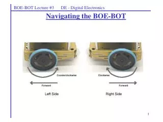
BOE-BOT Lecture #5 EGR 120 – Introduction to Engineering. Navigating the BOE-BOT with infrared sensors. Reference : For more complete documentation, the following items are available from www.parallax.com or www.tcc.edu/faculty/ webpages/PGordy. Robotics with the BOEBOT Version 2.2

E N D
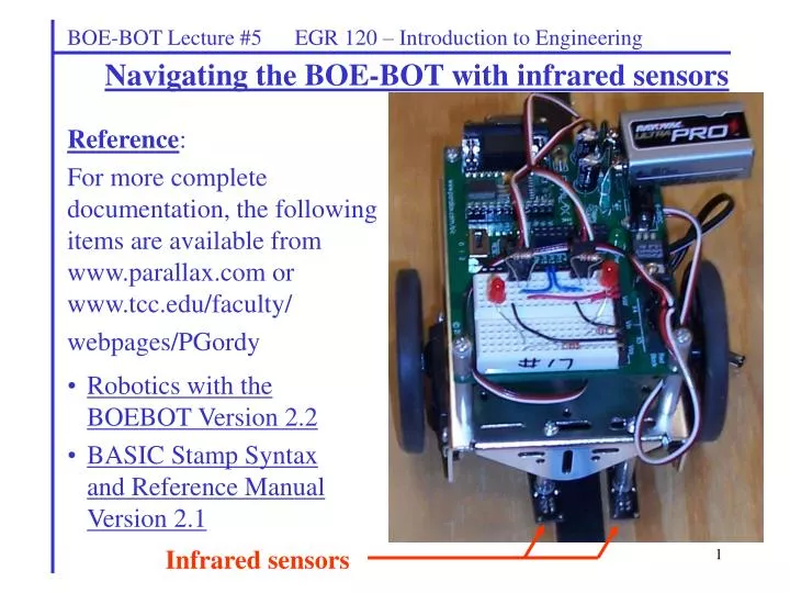
BOE-BOT Lecture #5 EGR 120 – Introduction to Engineering Navigating the BOE-BOT with infrared sensors Reference: For more complete documentation, the following items are available from www.parallax.com or www.tcc.edu/faculty/ webpages/PGordy • Robotics with the BOEBOT Version 2.2 • BASIC Stamp Syntax and Reference Manual Version 2.1 Infrared sensors
BOE-BOT Lecture #5 EGR 120 – Introduction to Engineering Infrared Navigation with the BOE-BOT(Line following) The following is an excerpt from Robotics, Version 2.2: “Today’s hottest products seem to have one thing in common: wireless communication. Personal organizers beam data into desktop computers, and wireless remotes let us channel surf. Many remote controls and PDA’s use signals in the infrared frequency range to communicate, below the visible light spectrum. With a few inexpensive and widely available parts, the BASIC Stamp can also receive and transmit infrared light signals.”
BOE-BOT Lecture #5 EGR 120 – Introduction to Engineering 3
BOE-BOT Lecture #5 EGR 120 – Introduction to Engineering • Infrared sensor circuits • The sensor circuit consists of an infrared diode (transmitter) and a phototransistor mounted in a housing. • The infrared diode shines a beam downward onto the track. • The beam bounces off the track and is received by a phototransistor (receiver). • The sensor circuit can detect the difference between light-colored surfaces and dark-colored surfaces by the amount of light that is reflected. Infrared light bounces off track surface 0.25” Critical Distance
BOE-BOT Lecture #5 EGR 120 – Introduction to Engineering Navigating with infrared sensors There are many possible approaches to navigation using infrared sensors. One approach is described below. • Basic navigation method: • If the left sensor hits the tape, turn left (slow the left wheel). • If the right sensor hits the tape, turn right (slow the right wheel). • How much should each wheel be slowed? It depends on: • The speed of the BOE-BOT. • The sharpness of the turn.
6 BOE-BOT Lecture #5 EGR 120 – Introduction to Engineering • Possible improvements for line following: • Note that if the BOE-BOT needs to make very sharp turns, then it will tend to jerk back and forth on straight sections as it is not capable of more gradual turns. Other approaches to improve the BOE-BOT’s performance would include: • Adding more sensors. The innermost sensors might be used for gradual turns and the outer sensor for more drastic turns. • Adjust the spacing between the sensors. • Rather than assigning a specific turning radius to a given sensor, the program could be modified to increment or decrement the Duration of the PULSOUT command. For example, if the left sensor hits the tape, turn a little more left. If it is still hitting the tape, turn even sharper left, etc. • Each sensor could be turned ON just before it is read (and all others turned OFF) to eliminate interference from the other sensors.
BOE-BOT Lecture #5 EGR 120 – Introduction to Engineering Mounting QTI sensors on the BOE-BOT • Mount two QTI sensors on the front of the BOE-BOT as illustrated to the right. • Space the two sensors so that they just straddle a piece of ¾” black electrical tape as shown below.
8 Connect Black wire to B Connect White wire to W BOE-BOT Lecture #5 EGR 120 – Introduction to Engineering Connecting cables to the QTI sensors The cables that are connected to the cables can easily be reversed, so care must be taken to connect them correctly.
BOE-BOT Lecture #5 EGR 120 – Introduction to Engineering Wiring the QTI sensors • Unfortunately, the QTI sensor cables cannot be used in the servo ports on the BOE-BOT since the cables from the QTI sensors do not have 5V in the same position as the cables from the servos. • As a result, a header should be used to connect each QTI sensor cable to the breadboard on the BOE-BOT. Plug header into end of QTI sensor cable. The header will then be plugged into the breadboard on the BOE-BOT. 9
VDD 10kΩ Left Sensor P9 VDD 10kΩ P8 Right Sensor BOE-BOT Lecture #5 EGR 120 – Introduction to Engineering Wiring the QTI sensors Each QTI sensors should be wired on the breadboard as indicated below.
11 BOE-BOT Lecture #5 EGR 120 – Introduction to Engineering Wiring the QTI sensors A picture of a breadboard with two wired QTI sensors is shown below. Note the connections listed to the right: • A cable from each sensor is plugged into the breadboard using a header. • The black wire from each cable is connected to Vss (ground). • The white wire from each cable is connected to Vdd (+5V). • The red wires from the cables are connected to P8 (right sensor) and P9 (left sensor). • A 10 k resistor (brown-black-orange) is connected between the red wire and the white wire for each cable. • LEDs have been added to test each sensor. An LED for the right sensor is connected to P1 and then to a 220 resistor (red-red-brown) to Vss (ground). The left sensor similarly uses P15.
BOE-BOT Lecture #5 EGR 120 – Introduction to Engineering Navigating with QTI infrared sensors – Sample program Adjust these values so that it can make the sharpest right turns, yet not slow down too much. Adjust these values so that it can make the sharpest left turns, yet not slow down too much. Adjusting these values so that your BOE-BOT travels straight. This will keep it from “hunting” on the straight sections.
BOE-BOT Lecture #5 EGR 120 – Introduction to Engineering • The BOE-BOT is ready to navigate the track by following the black lines. • The right LED should turn on every time the right sensor moves over the tape. • The left LED should turn on every time the left sensor moves over the tape. 13