Download
1 / 26
260 likes | 447 Views
AMR. Automatic Meter Reader. By: Power Communication Systems (PCS, Inc.). Team Members. #1Advisor. Dr. Noel Schulz. “ The Fab-Five ”. Members: Daven Carter,, Samuel Jefferson III, Derrick Cherry, & Brian Wells Team Leader: Marc Lewis. Problem:.

E N D
AMR Automatic Meter Reader By: Power Communication Systems (PCS, Inc.)
Team Members #1Advisor Dr. Noel Schulz “ The Fab-Five ” Members: Daven Carter,, Samuel Jefferson III, Derrick Cherry, & Brian Wells Team Leader: Marc Lewis
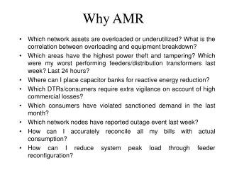
Problem: The existing automatic meter reading systems used to monitor power usage are extremely expensive. • Costly Installation • Costly Communication Techniques • The conventional meter reading systems are expensive to maintain and lack competitive qualities. • lack accessibility in bad weather conditions • Do not optimize network • Costly to read • Lack security tactics
AMR Benefits • Lower cost • Increase revenues • Decrease installation time • Reduce the amount of installed equipment • Increase Readings • Decrease Tamperings • Optimize Network (Create Competitive Advantage)
Block Diagram Comparator Hex Schmitt-Trigger Inverter Infrared Sensor Meter Amp PIC PC Wireless Communication Module
AMRHardware Components Comparator PIC w/ built-in A/D Converter Creatalink 2XT Module (Motorola) Infrared Sensor Meter PC
Design Requirements 1.AC Voltage:The system will be powered by the 220 VAC service entering the power meter. 2. Emission: The infrared emitter/detector must be at a distance of 1 cm away from the disk in order for the proper amount of light power to be detected by the phototransistor. 3. Performance: The system will detect 97% correct events at 16 RPM under normal operational conditions.
Design Requirements (cont.) 4.Signal Quality of Input to Transducer: The output of the sensor must be filtered in order for the modulated 40 kHz signal so that the SNR will be at least 16 dB. 5. Interface Between PIC and Wireless Board: The PIC and the Creatalink will be interfaced using three-wire RS232 Serial Communication protocol. The flow control between the two devices will be a software addition to the PIC. 6. Durability: This device must operate at the temperature range of -30 to 85 C. It must be protected against 1000 surges of 3000 A. It must also be waterproof and rust proof for up to 1 year per application of an anticorrosive chemical.
Design Requirements (cont.) 7.Packaging: Our device will be around 3 ½ x 1.5 inches and will be retrofitted into the case that holds existing watt meters, which has a circular area of 19.5 in². 8. Battery Back Up: Battery back up must be able to comply with the typical annual time of outages for most utilities: 4.08 hours 9. Cost: Typical AMR-related savings can be anywhere from $200 to $400 per meter per year, depending upon utility size, geography, labor rates, and meter accessibility 10. Longevity: The retrofit device has a lifetime expectancy of 25 years
Design Requirements for Prototype: • Emission • Performance • Cost
Additional Design Requirements for Packaged Product: • Battery Back Up • Packaging • Interface Between PIC and Wireless Board • Signal Quality of Input to Transducer
Sensor reflecting off of disk Light being detected by sensor
PIC Programming(ASM language): • Power Consumption • Outages • Time of use
I/O Circuit Board RS232 Interface Micro Processor Onboard Port Circuitry Power Supply Infrared Sensor • Link between Creatalink and PIC • Infrared Sensor & Transducer Circuitry • Onboard Re-Programmer
The Creatalink(Self- Addressing) • Operating Frequency: 929-932 MHz • Transmit Data Bits Rate: 1600, 3200, 6400 bps • Operating Temps: 5 to 40 C • Physical Dimensions: 56mm(L) x 20mm(W) x 12mm (H) • Supply voltage: 1.2 – 1.5 Vdc: 3.1 Vdc +/-100 mV • Interface: 14 pin connector, universal SMT
Summary Our solution is less expensive and quicker to install than alternatives. Our system offers comparable control and reporting capabilities as the competition. Our system is more appealing to small utilities.
Acknowledgements Advising: • Dr. Noel Schulz – Mississippi State University Assistance: • Dr. Randy Follett- Mississippi State University • Dr. Roger King – Mississippi State University • Dr. Joseph Picone – Mississippi State University • Dr. Robert Reese- Mississippi State University • Dr. Charles Nunnally- Virginia Tech University • Dr. Ray Winton- Mississippi State University • Mr. Bill Echols – SkyTel • Mr. Odie McHann – Mississippi State University • ABB – Meter Manufacturer
References [1] Bimal K. Base, “Energy, Environment, and Advances in Power Electronics,” IEEE Transactions on Power Electronics, Vol. 15, No. 4, pp. 688-701, July 2000. [2] A. Cohen, “Computers in use by Country,” Sales and Marketing Management, Vol. 150, No. 3, p.14, March 1998. [3] C. Brown, “Home Smart Home,” Black Enterprise, Vol. 27, No. 8, pp. 87-89, March 1997. [4] M. Shwehdi, “A Power Line Data Communications Interface Using Spread Spectrum Technology In Home Automation,” IEEE Transactions on Power Delivery, Vol. 11, No. 3, pp. 1232-1237, July 1996. [5] J. Douglas, “The Future of Metering,” EPRI Journal, Vol. 10, No. 7, pp 19-23, March/April 1998.
References (cont.) [6] Tom D. Tamarkin, “Automatic Meter Reading,” Public Power, Vol. 50, No. 5, September – October 1992. [7] R.C. Lanphier, Electric Meter History and Progress, Sangamo Electric Company, Springfield, Illinois, 1925. [8] Friese, “Three utilities announce AMR deployments,” Electric Light and Power, Vol. 7, No. 7, July 1998. [9] J. Newbury and W. Miller, “Potential Metering Communications Services Using Public Internet,” IEEE Transactions on Power Delivery, Vol. 14, No.4, October 1999. [10] A.J. Baldwin and N.G. Planer, Evaluation of Electrical Interference to Induction Watt-hour Meter, Honewell Inc., Roseville, Minnesota 1982.
References (cont.) [11] Rochelle A. Fischer, Aaron S. Laakonen, and Noel N. Schulz, “A General Polling Algorithm Using a Wireless AMR System for Restoration Confirmation,” IEEE Transactions on Power Systems, Vol. 16, No. 2, May 2001. [12] Krishna Sridharan and Noel N. Schulz, “Outage Management through AMR Systems Using an Intelligent Data Filter,” IEEE Transactions on Power Systems, Vol. 16, No. 2, May 2001. [14] Bruce A. McKenzie and Gerald L. Zachariah, Understanding and Using Electricity, Interstate Printers & Publishers, Inc., Danville, Illinois, 1982.