Download
1 / 37
380 likes | 540 Views
Webcutter Estimated time required: 40 min GUI familiarity level required: Lower. MSC.ADAMS 2005 r2. Topics Covered. In this tutorial, you will learn how to:. Save/Export Rotate Parts Add 2 Body, 2 Location Revolution Joint Save Assembled Model Modify Material Properties

E N D
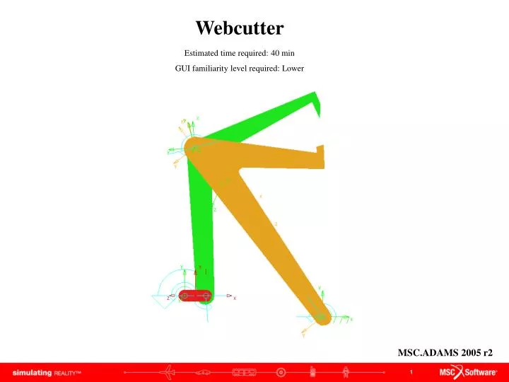
WebcutterEstimated time required: 40 min GUI familiarity level required: Lower MSC.ADAMS 2005 r2
Topics Covered In this tutorial, you will learn how to: • Save/Export • Rotate Parts • Add 2 Body, 2 Location Revolution Joint • Save Assembled Model • Modify Material Properties • Measure Torque, Bearing Force, CM angular Acceleration/Velocity • Measure Angle With Respect to Ground • Export Data to Excel • Create A step Function • Start Adams • Change Grid Size and Spacing • Set material Properties • Create Extruded Part • Modify Part • Rename • Modify View • Create Marker • Add Revolute Joint • Add Rotational joint Motion • Verify Model • Run Simluation You will need to download “link_geometry.zip” file to complete this tutorial If you have any difficulties, import the “Webcutter_shortcut_1.cmd” file and proceed from pg 18 If you have any difficulties, import the “Webcutter_shortcut_2.cmd” file and proceed from pg 21 If you have any difficulties, import the “Webcutter_Asm_shortcut_3.cmd” file and proceed from pg 26 If you have any difficulties, import the “Webcutter_Asm_shortcut_4.cmd” file and proceed from pg 34 If you have any difficulties, import the “Webcutter_Asm_complete.cmd” file and proceed from pg 25
Problem Title B4 B3 A2 O4 O2 This tutorial will describe in depth how to use ADAMS to determine the torque of the motor, bearing forces, and the angular position, velocity, and acceleration of the links for the given problem. Links are 2cm thick and made out of Al 6063. Link 2 is rotating at a rate of 60 rpm CCW.
What You Should Accomplish If you are successful, you should end up with a simple working webcutter model that illustrates bearing force, motor torque and angular velocity/acceleration of your model.
Create New Model Getting Started: a. Under the heading "How would you like to proceed", select the Create a new model radio button. b. Choose a Location to save your files c. Set Model Name as Webcutter d. Verify the Gravity text field is set to Earth Normal (-Global Y). e. Verify that the Units text field is set to MKS - m,kg,N,s,deg. f. Select OK. a b c d e f
Change Working Grid Settings • To edit the grid size: • Click Settings menu, select Working Grid… • The Working Grid Settings window will appear • Change the Spacing text fields in X and Y to (10mm) • Click OK • Click View Coordinate Window (F4) a b d c Note: you should see a denser set of dots on your screen
Set Material Properties • A new window will appear, enter: • Name: .Webcutter.Al6063 • Young Modulus: 214e6 • Poissons Ratio: 0.33 • Density: 2710 • Click OK • Click Build Menu Materials New a b c Note: If the density is not set the simulation will not run properly
Create Extruded Part • Right click on Rigid body tool stack, select Extrusion tool • Enter 0.02 in the Length text field • Select Backward from Path: drop down menu • Click points origin (0.0, 0.0, 0.0) (0.15, 0.15 0.0) (0.15, 0.0, 0.0) (0.0, 0.0, 0.0), right-click to close a d c b Note: When using a command the bar on the bottom will tell you what to do and you can always exit a command by pressing the Esc key
Change View • Right Click in the workspace and Select Iso <I> or Press Shift+I to view an isometric view. a Various other options and their shortcut keys are available in this menu. Spend some time experimenting with them and then return to the front view (Shift+F)
Rename • Right-Click on part, select Part: PART_2 Rename • Enter .model_1.link_2 in New Name text field • Click OK b c a • Rename the Marker at the origin to .model_1.O2
Modify Extrusion Points • Right-click on the triangle, select Extrusion: Extrusion_1 Modify. • Click next to Profile Points text field • Click Read button next to File • Browse the directory for the file link2.txt • Click Open • Click OK • Click OK a d b g e c f Note: By starting our Triangle at the origin and normalizing the points about O2 for link 2, the origin and O2 coincide.
Create a Marker • Right click on Rigid body tool stack, select Marker tool • Select Add to Part from Marker pull down menu • Select Global XY from Orientation pull down menu • Click Part_2 (0.04, 0.0, 0.0) • Rename Marker .model_1.A2 a b c d Note: This is why the links were rotated to make OA horizontal for the input files.
Add Revolute Joint • Right click Joint tool stack, select Revolute joint • Select 1 Location from Construction pull down menu • Click on point link_2.O2 a b c
Add Motion • Right Click on Motion Driver tool stack, select Rotational Joint Motion • Enter (360D) in Speed text field • Click JOINT_1 a c b
Verify Your Model a. In the lower right corner of the modeling window, right-click on the Information icon. b. Click on the Verification icon. a b • The Info Window appears • c. After seeing that the model has verified successfully, • d. click on the Close button d c Note: The model verification step is one way to find errors in the model definition. ADAMS checks for error conditions such as misaligned joints, unconstrained parts, or massless parts in dynamic systems, and alerts you to other possible problems in the model.
Run a Simulation • How to simulate the model: • Click on the Simulation tool in the Toolbox. • Select Duration from pull down menu • Enter 2 • Select Step Size from pull down menu • Enter 0.01 • Click on the Play button. • If everything has been done correctly the bar should complete one revolution. a c d b b
Save Database • Save your database by Click File Save Database, and select no for a backup copy a • To export a .cmd file • Click File Export • Select ADAMS/View Command File from File Type pull down menu • Enter a File name • Click OK c d b e
Create Part 2 • Create another extruded triangle, with thickness = 0.2, using points: • (0.04, 0.0, 0.0) (0.3, 0.0, 0.0) (0.25, -0.15, 0.0) • Modify Extrusion points using list3.txt • Rename the part to link_3 • Create Marker at Point (0.32,0.0,0.0), rename it B3 • Create a revolute joint between link_2 and link_3 d e
Revolve Part • Click anywhere on Link 3. Notice that everything is highlighted and there is a green handle at the end of the y axis on the coordinate located at A2. • Click on this handle and drag left. This causes Link 3 to rotate about that point. Let Link 3 in this position for now so it is out of the way. b a
Verify and Simulate • Verify you model • Run a simulation: Duration = 2.0, Step Size = 0.01 b a
Create Marker • Create Marker on the ground at point (0.26, -0.04, 0.0) • Rename it O4 a
Create Part 4 • Draw another triangle with the Extrusion tool this time with the first point at O4. Repeat the previous steps and read in Link4.txt to correct the shape. • Create a marker on link 4 at position (0.66, -4.0E-002, 0.0), rename it B4 • Add a Revolute Joint between link 4 and Ground, at O4. b c
Create Joint between Part 3 and 4 • Rotate link_4 so that points B3 and B4 are close • Click the revolute joint tool • Select 2 Bod-2 Loc from Construction pull down menu • Click link_4 link_3 (point) B4 (point) B3 d b c a
Rendering Model • Click View Render Mode Smooth Shaded • (This can also be done by using the shortcut keys or Shift <S>) a
Save Assembled Model • To join these location click Simulate Interactive Controls • Click which performs initial conditions solution. • Ignore and Close the warning that comes up. The part is now joined • Click • Enter .Webcutter_Asm in New Model text field, Click OK • Click play to run the simulation. a f e b d Note: The warning is stating that the two reference points of the revolute joint are not the same and need to be the same for the part to run. ADAMS will move the two links so that the points will coincide before running the simulation.
Modify Material Properties • Right-Click link 2, Select Part: link_2 Modify • Enter .Webcutter_Asm.Al6063 in Material Type text field • Click OK • Repeat this step for link_3 and link_4. b a c Note: If you choose the option of just entering density, the Links will have significant deformation during the run.
Model This is what your screen should look like when your model is complete.
Measure Motor Torque • Right Click Motion and select Motion: Motion_1 Measure • Enter .Webcutter_Asm.Torque in Measure Name text field • Select Torque from Characteristic pull down menu • Choose Z radio button next to Component. • Click OK (A measurement window will appear which will graph torque respective to the simulation b c d a e
Measure Bearing Forces • Right Click on revolute joint, Select Joint: JOINT_1 Measure • Enter .Webcutter_Asm.Bearing_Force_1 in Measure Name text field • Select Force from Characteristic pull down menu • Choose mag radio button next to Component. • Click OK b c d a e
Measure Angles of Links with Respect to Ground • Click Build Measure Orientation New. • Select .Webcutter_Asm.link_2_O2 for To Marker (Marker on Link 2) • Select .Webcutter_Asm.ground.MARKER_4 for From Marker (Marker on the Ground) • Click OK b c a d
Measure Angular Velocity and Acceleration • Right Click link_3, Select Part: link_4 Measure • Enter Webcutter_Asm.Ang_Acceleration • Choose CM Angular Acceleration select Z • Press Apply • Enter Webcutter_Asm.Ang_Velocity • Choose CM Angular Velocity select Z • Press OK b e c f a d g
Results • To create and view plots • Click Review Postprocessing (F8) • A new window will open • Select all measure and Click Add curves. b
Export Data to Excel • Click File Export Table. • Enter Webcutter in File Name text field • Select plot_1 (or whichever plot you are trying to export) in Plot text field • Select spreadsheet from Format pull down menu • Click OK • Rename file from Webcutter.tab to Webcutter.xls a b c d e
Creating a Step funciton • Right-click motion, seect Motion: MOTION_1 Modify • Click button next to Function (time) tet field • Enter STEP(time, 0, 0d, 1, 720d) in Define a runtime fucntion text field • Click Verify • Click OK • Click OK a c b d f e Note: The step function created is in the form: STEP(variable, starting time, starting position, ending time, ending position)
Verify and Simulate • Verify you model • Run a simulation: Duration = 2.0, Step Size = 0.01 b a Note: the model will stop running at 1sec, due to the STEP function
Topics Covered In this tutorial, you will learn how to: • Start Adams • Change Grid Size and Spacing • Set material Properties • Create Extruded Part • Modify Part • Rename • Modify View • Create Marker • Add Revolute Joint • Add Rotational joint Motion • Verify Model • Run Simulation • Save/Export • Rotate Parts • Add 2 Body, 2 Location Revolute Joint • Save Assemled Model • Modify Material Properties • Measure Torque, Force, CM Angular Acceleration/Velocity • Measure Angle With Respect To Ground • Export Data to Excel
Best Practices • Make sure the revolute joint is in the correctdirection. • Check dimensions of your parts to make sure they are correct. • Check mass properties to make sure they are correct. • Check orientation of the part to make sure it is correct. • Make sure your model verification is successful • Make sure the measures are set properly. • Make sure the plot is displaying the correct set of results.