Download
1 / 34
510 likes | 2.02k Views
A. .014 A B C. C. B. Tolerance of Position -- RFS.

E N D
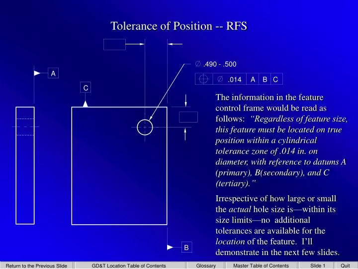
A .014 A B C C B Tolerance of Position -- RFS • The information in the feature control frame would be read as follows: “Regardless of feature size, this feature must be located on true position within a cylindrical tolerance zone of .014 in. on diameter, with reference to datums A (primary), B(secondary), and C (tertiary).” • Irrespective of how large or small the actual hole size is—within its size limits—no additional tolerances are available for the location of the feature. I’ll demonstrate in the next few slides. .490 - .500
Tolerance of Position -- RFS True Position • The exact location of the hole is established with basic dimensions.
.014 A B C Tolerance of Position -- RFS True Position • The cylindrical tolerance zone is established in the feature control frame –( .014). Location Tolerance Zone –RFS
.014 A B C Tolerance of Position -- RFS True Position • For the worst possible condition, • the hole axis is located at the extreme limit of the cylindrical tolerance zone. Location Tolerance Zone –RFS
.014 A B C Tolerance of Position -- RFS True Position • When the axis is located at the extreme limit of the tolerance zone, the MMC holeaxis would be offset from the true position by a distance equal to one-half of the position tolerance (.007). MMC Diameter Location Tolerance Zone –RFS (Always the Same)
.014 A B C Tolerance of Position -- RFS True Position • The actual hole size may vary between MMC (smallest diameter) and LMC (largest diameter), but the axis location cannot violate the boundaries of its location tolerance. MMC Diameter Location Tolerance Zone –RFS (Always the Same) LMC Diameter
.014 A B C Tolerance of Position -- RFS True Position • The white circle represents the MMC boundary. Its center is located at true position. No element of the hole surface can be inside this boundary. MMC Boundary (VC Functional Gauge) MMC Diameter Location Tolerance Zone –RFS (Always the Same) LMC Diameter
.014 A B C Tolerance of Position -- RFS LMC Boundary True Position • The outer white circle represents the LMC boundary centered on true position. No elements on the surface of the hole can be outside of this boundary. The following series of slides will sequence the progressive position of the center of the hole as it moves around the tolerance zone. MMC Boundary (VC Functional Gauge) MMC Diameter Location Tolerance Zone –RFS (Always the Same) LMC Diameter
.014 A B C Tolerance of Position -- RFS LMC Boundary True Position • The outer white circle represents the LMC boundary. No elements on the surface of the hole can be outside of this boundary. The following series of slides will sequence the progressive position of the center of the hole as it moves around the tolerance zone. MMC Boundary (VC Functional Gauge) MMC Diameter Location Tolerance Zone –RFS LMC Diameter
.014 A B C Tolerance of Position -- RFS LMC Boundary True Position • The outer white circle represents the LMC boundary. No elements on the surface of the hole can be outside of this boundary. The following series of slides will sequence the progressive position of the center of the hole as it moves around the tolerance zone. MMC Boundary (VC Functional Gauge) MMC Diameter Location Tolerance Zone –RFS LMC Diameter
.014 A B C Tolerance of Position -- RFS LMC Boundary True Position • The outer white circle represents the LMC boundary. No elements on the surface of the hole can be outside of this boundary. The following series of slides will sequence the progressive position of the center of the hole as it moves around the tolerance zone. MMC Boundary (VC Functional Gauge) MMC Diameter Location Tolerance Zone –RFS LMC Diameter
.014 A B C Tolerance of Position -- RFS LMC Boundary True Position • The outer white circle represents the LMC boundary. No elements on the surface of the hole can be outside of this boundary. The following series of slides will sequence the progressive position of the center of the hole as it moves around the tolerance zone. MMC Boundary (VC Functional Gauge) MMC Diameter Location Tolerance Zone –RFS LMC Diameter
.014 A B C Tolerance of Position -- RFS LMC Boundary True Position • The outer white circle represents the LMC boundary. No elements on the surface of the hole can be outside of this boundary. The following series of slides will sequence the progressive position of the center of the hole as it moves around the tolerance zone. MMC Boundary (VC Functional Gauge) MMC Diameter Location Tolerance Zone –RFS LMC Diameter
.014 A B C Tolerance of Position -- RFS LMC Boundary True Position • The outer white circle represents the LMC boundary. No elements on the surface of the hole can be outside of this boundary. The following series of slides will sequence the progressive position of the center of the hole as it moves around the tolerance zone. MMC Boundary (VC Functional Gauge) MMC Diameter Location Tolerance Zone –RFS LMC Diameter
.014 A B C Tolerance of Position -- RFS LMC Boundary True Position • The outer white circle represents the LMC boundary. No elements on the surface of the hole can be outside of this boundary. The following series of slides will sequence the progressive position of the center of the hole as it moves around the tolerance zone. MMC Boundary (VC Functional Gauge) MMC Diameter Location Tolerance Zone –RFS LMC Diameter
.014 A B C Tolerance of Position -- RFS LMC Boundary True Position • The outer white circle represents the LMC boundary. No elements on the surface of the hole can be outside of this boundary. The following series of slides will sequence the progressive position of the center of the hole as it moves around the tolerance zone. MMC Boundary (VC Functional Gauge) MMC Diameter Location Tolerance Zone –RFS LMC Diameter
Tolerance of Position -- MMC • The next example will illustrate the concept of bonus tolerance, in connection with position tolerances. We will use the same drawing example that was used to discuss tolerances of position, when applied regardless of feature size (RFS). One of the significant differences you will see is the advantages of defining the tolerance zone for the axis of a hole as we did before—but this time, we will add the modifier for maximum material condition (MMC) to the tolerance specification in the feature control frame. Notice the changes that occur in location tolerances when modifiers are used, and as departure from MMC occurs.
A C B Tolerance of Position -- MMC • The information in the feature control frame would be read as follows: “This feature must be located on true position within a cylindrical tolerance zone of .014 on diameter with reference to datums A (primary), B (secondary), and C (tertiary), when the hole is at its smallest size, or MMC.” • As the actual hole size increases in size from MMC, additional tolerance (equal to the amount of departure) may be added to the location tolerance for the feature. .490 - .500 .014 A B C M
Tolerance of Position -- MMC True Position • The exact location of the hole is established by basic dimensions.
Tolerance of Position -- MMC MMC Diameter (Axis at Maximum Offset) True Position • The maximum material condition diameter of .490 is shown at its maximum offset from true position—one-half the specified location tolerance.
Tolerance of Position -- MMC MMC Diameter True Position • As the size of the hole changes within its tolerance range from MMC—smallest hole size limit, and increases in size towards the LMC, or upper size limit, an equal amount of tolerance can be added to the axis location tolerance. Location Tolerance Zone at LMC
Tolerance of Position -- MMC MMC Diameter True Position • The additional tolerance for the hole axis location (which is equal to the amount of departure from MMC), is called “bonus tolerance.” LMC Diameter Bonus Tolerance Location Tolerance Zone at LMC
Tolerance of Position -- MMC MMC Diameter True Position • When the hole size is at its lower limit (MMC), and positioned at the extreme limit of the MMC location tolerance, the MMC boundary is established. When the feature of size is at this limit, no elements of the hole surface may be inside this theoretical boundary. This is the virtual condition of the hole, which also simulates the mating part at its maximum material condition. LMC Diameter MMC Boundary Location Tolerance Zone at LMC
Tolerance of Position -- MMC MMC Diameter True Position • When the hole size is at its upper limit (LMC), and positioned at the extreme limit of the location tolerance, the LMC • boundary is • established. • No elements of • the hole surface • can be out-side • this boundary. LMC Diameter MMC Boundary LMC Boundary Location Tolerance Zone at LMC
Tolerance of Position -- MMC MMC Diameter True Position • In this next series of slides, note that while the size and location of the actual hole may vary, the elements on • the surface of the holes • never violate their • boundaries. This • series will help • you to understand • how the hole size • changes can affect • the location of the • center axis—and its orientation. LMC Diameter MMC Boundary (VC=MMC-Tol) LMC Boundary Location Tolerance Zone at LMC
Tolerance of Position -- MMC MMC Diameter True Position • Axis location variance possibilities when position tolerance is modified to MMC. LMC Diameter MMC Boundary (VC=MMC-Tol) LMC Boundary Location Tolerance at MMC Location Tolerance at LMC Location Tolerance at LMC
Tolerance of Position -- MMC MMC Diameter True Position • Axis location variance possibilities when position tolerance is modified to MMC. LMC Diameter MMC Boundary (VC=MMC-Tol) LMC Boundary Location Tolerance at MMC Location Tolerance at LMC Location Tolerance at LMC
Tolerance of Position -- MMC MMC Diameter True Position • Axis location variance possibilities when position tolerance is modified to MMC. LMC Diameter MMC Boundary (VC=MMC-Tol) LMC Boundary Location Tolerance at MMC Location Tolerance at LMC Location Tolerance at LMC
Tolerance of Position -- MMC MMC Diameter True Position • Axis location variance possibilities when position tolerance is modified to MMC. LMC Diameter MMC Boundary (VC=MMC-Tol) LMC Boundary Location Tolerance at MMC Location Tolerance at LMC Location Tolerance at LMC
Tolerance of Position -- MMC MMC Diameter True Position • Axis location variance possibilities when position tolerance is modified to MMC. LMC Diameter MMC Boundary (VC=MMC-Tol) LMC Boundary Location Tolerance at MMC Location Tolerance at LMC Location Tolerance at LMC
Tolerance of Position -- MMC MMC Diameter True Position • Axis location variance possibilities when position tolerance is modified to MMC. LMC Diameter MMC Boundary (VC=MMC-Tol) LMC Boundary Location Tolerance at MMC Location Tolerance at LMC Location Tolerance at LMC
Tolerance of Position -- MMC MMC Diameter True Position • Axis location variance possibilities when position tolerance is modified to MMC. LMC Diameter MMC Boundary (VC=MMC-Tol) LMC Boundary Location Tolerance at MMC Location Tolerance at LMC Location Tolerance at LMC
Tolerance of Position -- MMC MMC Diameter True Position • Axis location variance possibilities when position tolerance is modified to MMC. LMC Diameter MMC Boundary (VC=MMC-Tol) LMC Boundary Location Tolerance at MMC Location Tolerance at LMC Location Tolerance at LMC


![HR for RFS [GSE2034 data]](https://cdn3.slideserve.com/5632256/slide1-dt.jpg)