Download
1 / 11
110 likes | 189 Views
Transfering Trigger Data to USA15. V. Polychonakos , BNL. Introductory Comments. Huge advantage if trigger data transfer to USA15 logic can be implemented on the detectors Harvard Scheme is fine Adds complexity, cost, weight Details needed, latency?

E N D
Transfering Trigger Data to USA15 V. Polychonakos, BNL
Introductory Comments • Huge advantage if trigger data transfer to USA15 logic can be implemented on the detectors • Harvard Scheme is fine • Adds complexity, cost, weight • Details needed, latency? • Can it run synchronously with BC clock? • Needs serializer • The need for serializer prompted us to change the ART output from parallel to serial LVDS. Gianluigi agrees, suggests scheme shown in next slide • The need for a custom digital ASIC triggered a reevaluation of the idea of direct on-detector transfer • Serial ART allows point to point connections avoiding a parallel bus (one of John’s objection to the scheme)
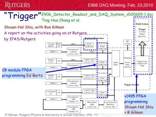
50ns 100ns 150ns 200ns 25ns 75ns 125ns 175ns VMM ART SERIALIZER - v2 analog pulse reset charge event peak-found CK A FL D5 - D0 Assumes 160 MHz clock provided externally ART serialized in one line A Data D5-D0 shifted at each clock edge LVDS600mV +/- 150mV
The transfer scheme in bullets • Point to point LVDS connections from the serial ART of 32 ICs (one layer of a “panel”) to a mezzanine board at the middle of the chamber (or perhaps part of a MMFE – average length of copper connections ~fewcm) • Custom digital IC connected to a GBT operating in parallel mode (40 bit bus at 80 MHz transfers 80 bits in 25 ns) • For a given BC (the event BC) the flags of all ART signals arrive within the 25 ns of the event BC • Clocked by the rising edge of the next BC synchronizes the flags while some serial streams will finish arriving in the next bunch crossing • In the next to the event BC a priority encoding scheme or smart token builds a list of up to 6 hit addresses • A state machine operates on this list in the next BC and transfers them to the GBT at 80 MHz • Each 40 bit word contains up to 3 ART addresses (33 bits) plus 6 bits of the 12 bit BCID, high order in the first 40 bit word, low order in the second • Note that the ART in a given BC will be inactive in the next BC all others in the 32 IC group are active (we impose a dead time of a few BC any way) • Total latency is 2 BC clock ticks • GBT in parallel mode adds 5 BC ticks (2 seraliser, 3 deserialiser)
High Level Block Diagram GBT also provides the 80, 160 and, if needed, the 320 MHz Clocks
An alternative way (suggested by Sorin) to transmit the ARTs (Eliminates ambiguity with address 00) DOUT[39:0] A5 – 11 bits A12 – 11 bits BCID/ART A2 – 11 bits DOUT[79:40] empty empty BCID/ART A16 – 11 bits “000....00000” “000....00000” VMM 0, STRIP 0 32-bit hit list 12 2 5 16 DOUT[39:0] BCID/ART B.. DOUT[79:40] ART-6bits ..CID/ART ART-6bits ART-6bits ART-6bits empty
A Possible implementation of the address transfer (WEN) (EN)
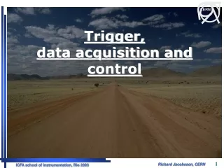
Group ICs from the four layers of a multilayer (4 8-chip MMFEs) Front end boards Trigger Board Possible location minimizes lvds lines to few cm, with adjacent group can use dual versatile link
What’s next? • Scheme needs to be scrutinized for errors, wrong assumptions, etc • A Flag priority encoding or other scheme to identify up to 6 ART addresses (needs to be done in 25 ns, but maybe not if more than one BC of dead time is imposed ) • Then write VHDL code and implement it on FPGA • Can have such a prototype by the time of VMM2 • If convinced it works transfer the code to a custom design