Download
1 / 81
1.09k likes | 1.53k Views
Quality Assurance and Nondestructive Evaluation of Composite Materials . Outline, Section 2. Design and Detectability Manufacturing and Fabrication Testing-NDT In-Service Inspection-NDT Damage Assessment and Repair Inspection Visual Inspection Typical Conditions-Laminates

E N D
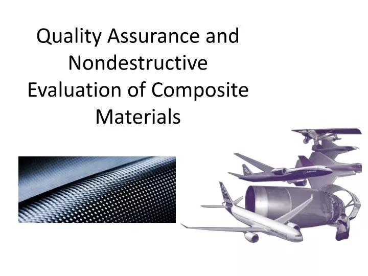
Quality Assurance and Nondestructive Evaluation of Composite Materials
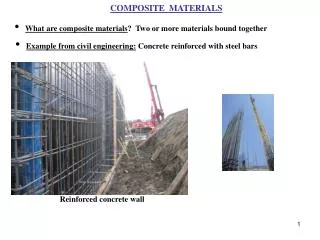
Outline, Section 2 • Design and Detectability • Manufacturing and Fabrication Testing-NDT • In-Service Inspection-NDT • Damage Assessment and Repair Inspection • Visual Inspection • Typical Conditions-Laminates • Typical Conditions-Honeycomb • Mechanical Methods • Measuring composites • Tools, UT Thickness, Magnamike • Acceptance Criteria • Fiberglass and translucent materials, Hot light Inspection • Manual and Automated Tap Test • Inspecting known damage • Foreign Material, Foreign Object Detection, (FOD), Foreign Object Evaluation and/or Elimination (FOE)
Design, Section 2 The strength of any given laminate under a prescribed set of loads is probably best determined by “conducting a test”. However, when many laminates and different loading conditions are being considered, as in a preliminary design study, analysis methods for estimation of laminate strength become desirable. Because the stress distribution throughout the fiber and matrix regions of all the plies of a laminate is quite complex, precise analysis methods are not available. However, reasonable methods do exist which can be used to guide the preliminary design process.
Design, Section 2 • Key Design Considerations • Material Selection • Processing/Fabrication Methods • Structural Considerations • Environmental Effects & Protection • Sandwich Construction
Design, Section 2 Aircraft Composite Design Process • Determine requirements and loads • Select structural configuration • Select material, fabric, thickness, style, ply sequence • Calculate laminate properties Strength, stiffness, strain to failure, etc • Calculate stress induced by loads Go back to 3 if stress × 1.5 >1 • Evaluate cost versus weight Go back to 2 if high cost or weight • Build & test prototype – final design
Design, Section 2 Design concern example: With failure rates still high for turbine blades (a Sandia Lab survey of wind energy plants documented rates as high as 20% failure) and down-time costly and bad for business, blade designers and manufacturers have turned to the best practices for designing composites.
Design, Section 2 • Select Structural Configuration • Important to have a thorough knowledge of the advantages and disadvantages of the various fabrication / manufacturing techniques • Design for Manufacture • Usually a specific structural configuration is selected for • Ease of construction • Low tooling and fabrication costs • Lightweight • Once the type of composite structure has been selected = preliminary structural sizing of the components and laminates can proceed • Using standard structural analytical techniques • Together with simple optimization techniques and equations
Design, Section 2 Design and Analysis of Structures • Analysis of composite components is difficult • Dynamic loads are especially hard to consider • Design tools are less developed than those for conventional materials • Testing is still widely used to validate design and analysis models
Design, Section 2 Design concerns of Composites • Environmental degradation of resin dominated properties • Notch sensitivity • Impact damage • Poor through thickness properties • Variability • Properties not established until manufactured • Limited availability of design data • Reinforcement incorrectly located • Lack of codes and standards • Recycling not easy • Fire, smoke and toxicity performance
Design, Section 2 Further design Considerations of Composites • Textured surfaces • Self coloring • Integration of parts • Economy of scale • Molding direct to final dimensions • Efficient use of materials • Durability • Lifetime costing attractive
Design, Section 2 Typical aerospace composite manufacturing processes consist of filament winding, fiber placement, pultrusion, tape laying, tape wrapping, press molding, hand layup and resin transfer molding. Uses of Fiber/Matrix
Design, Section 2 Summary of Composite Manufacturing Processes
Design, Section 2 PREPREG PRODUCTION PROCESS Pultrusion
Production Inspection, Section 2 NDE Techniques for Detecting Defects in Composite Materials 1. Filament winding 5. Tape wrapping 2. Fiber placement 6. Press molding 3. Pultrusion 7. Hand layout 4. Tape laying 8. Resin transfer molding
Detection, Section 2 Composites tend to fail in a different way to metals Failure modes • Brittle fibres in a ductile matrix • Sudden brittle failure – no elasticity • Crazing and matrix cracking may occur • Unseen failure may initiate in the laminate • Hence fear due to BVID in carbon fiber structures • Inter laminar disbonding and damage
Detection, Section 2 This figure illustrates the interrelationship between key factors involved in the concept of inspection reliability. A detailed discussion in these issues falls outside the scope of this overall view. Pertinent information can be found elsewhere /1/. However, while some traditional notions shown may seem self-explanatory for inspection practitioners other, wide or closely related with the trends of NDT-reliability improvements, deserve to be outlined. /1/V. Schmitz, K.J. Langenberg, W. Kappes, M. Kröning: "Inspection procedure assessment using modeling capabilities" Nuclear Engineering and Design,
Detection, Section 2 With the new developed modeling algorithms, practically the whole NDT testing technique can be covered. The NDT modeling systems developed under the logo of CAI (Computer Aided Inspection) are a combination of modeling the geometry and material response of the inspected component together with the testing techniques and its scanning parameters.
Detection, Section 2 Accurate NDE methods are considered a necessity to ensure aircraft airworthiness and passenger safety. Traditionally, tap tests and a few ultrasonic-based inspection methods have been used to inspect composite aircraft structures.
Detection, Section 2 Categories of Damage & Defect Considerations for Primary Composite Aircraft Structures
Detection, Section 2 A test program, called “Composite Flaw Detection Experiments”, was undertaken at the Federal Aviation Administration (FAA) Airworthiness Assurance NDI Validation Center (AANC), operated by Sandia National Laboratories. A large number of test panels, representing the detrimental conditions of construction on aircraft, were inspected using a wide array of NDE techniques. Forty-four Nomex honeycomb core panels with either carbon/epoxy or fiberglass/epoxy skins were manufactured, with flaws ranging from 0.2 in² to 3 in² (1.29 cm² to 19.35 cm²). F The panels were shipped to airlines, third-party maintenance depots, aircraft manufacturers and NDE developer labs around the world. Industry-wide data was generated to quantify how well current inspection techniques are able to reliably find flaws in composite honeycomb structure. [Roach, 2010] The program developed Probability of Detection (PoD) curves for various laminates and NDE techniques. Results from the “round-robin” detection study are shown.
Detection, Section 2 The reliability of inspection techniques may be understood and quantified in probabilistic terms. Broadly speaking the inspection reliability is defined as the probability of not overlooking an existing defect (probability of detection, POD) and correct sizing the defect. Whatever simple this definition may appear, it encompasses many complex issues ranging from the specification of the nature of defects to influencing factors related with the inspection instrumentation, product nature, the involved human factor and the available expertise for inspection data processing and assessing.
Detection, Section 2 Typical reference standard and/or probability of detection sample
Detection, Section 2 Least opportunity for detection Best opportunity for detection Probability of Detection (PoD) versus flaw size (diameter in inches) for composite sandwich panels with various skin architectures
Detection, Section 2 Aerospace Damage and Repair Inspection Procedures • Methods used in the field for aerospace composite part damage detection, damage characterization, and post-repair inspection are typically less sophisticated than those employed by the OEM for their post-processing inspection. Operators and maintenance organizations use visual inspection as their main technique for initial detection of field damages, unless NDE techniques are specified by the specific maintenance planning manual or aircraft maintenance manual. Once damage is detected visually, other NDE methods are typically used to map the full extent of damage for proper disposition.
Detection, Section 2 • In addition to the use of visual inspection to first detect damage, more sophisticated NDE methods are essential to the subsequent damage disposition and repair processes. Many types of damage have both visual and hidden damages. Hidden damage in composites usually covers a larger area than visual indications of damage is most responsible for lost residual strength. • It is essential that the proper NDE methods be applied to damage found on aerospace composite structure to map the full extent of the damage, which is needed to determine whether damage is below the Allowable Damage Limit (next slide) or whether repairs are required. Since a disposition of repair size limits also depends on accurate mapping, decisions on whether the repair substantiation database is sufficient also relies on a complete inspection with the proper NDE.
Production Inspection, Section 2 We need a general understanding before we begin our inspection! Can the inspection technique detect the suspected imperfection(s)? Are there reference standards? What is the inspection criteria? Is there a FOE or FOD program required? What is the minimum detectable vs. minimum rejectable ? What is the direction of loading and suspect flaw location? Customer Requirements? What are the qualification and certification requirements? What is the best inspection method? What is the inspection requirement? What is the Material? What process was used to fabricate? What type of defects can be produced?
Production Inspection, Section 2 Testing: • Component, subcomponent, and generic structural tests are performed to verify analysis. • Particular component tests may include elements of aerodynamics, vibro acoustic and thermal loading conditions, as well as significant externally applied mechanical loads. • Subcomponent tests may be performed for critical areas of the component. • Generic tests include flange and stiffened panel tensile tests, damage tolerance tests, and standard temperature effect tensile and compressive coupon tests.
Production Inspection, Section 2 Planning the inspection points
Production Inspection, Section 2 Inspection: Quality assurance for composite parts centers on techniques for validating the physical and mechanical properties of a cured composite. However, quality assurance begins long before the end item is tested. A logical approach to quality control follows the fundamentals of composite reaction control: • raw material validation reaction control; • material characteristics; • In process fabrication/handling/tooling effects; • cure process control and documentation; • Post cure machining. Visual inspection is used to inspect bond lines that are visible in the various bond stages and to detect any visible surface discontinuities and/or delaminations. Mechanical inspection is used to verify design dimensions, acoustics, input resistance, static loads and dynamic loads. Nondestructive evaluation is perhaps the most important inspection technique for determining defects in composites, particularly the defects specified in Table
Production Inspection, Section 2 Typical Process Flow
In-Service & Repair Inspection, Section 2 REPAIR OPTIONS When a composite structure sustains damage in service one of three levels of repair must be employed. Cosmetic repair • In this case inspection has determined that the damage has not affected the structural integrity of the component. A cosmetic repair is carried out to protect and decorate the surface. This will not involve the use of reinforcing materials. Temporary or interim repairs • It is often the case in service, that small areas of damage are detected which in themselves do not threaten the integrity or mechanical properties of the component as a whole. However if left unrepaired they may lead to further rapid propagation of the damage through moisture ingress and fatigue. Simple patch type repairs can be carried out, with the minimum of preparation, to protect the component until it can be taken out of service for a proper structural repair. Temporary repairs should be subject to regular inspection. Structural repair • If the damage has weakened the structure through fibre fracture, delamination or disbonding the repair will involve replacement of the damage fibrereinforcement, and core in sandwich structures, to restore the original mechanical properties. Since a bonded-on repair constitutes a discontinuity of the original plies, and therefore a stress raiser, structural repair schemes normally require extra plies to be provided in the repair area. If the damaged area is very small it can be questionable whether a structural repair, requiring removal of a substantial amount of the structure in damage removal and preparation, is preferable to a cosmetic repair.
In-Service & Repair Inspection, Section 2 Typical Damage • Most damage to fiber reinforced composites is a result of low velocity and sometimes high velocity impact. In metals the energy is dissipated through elastic and plastic deformations and still retains a good deal of structural integrity. While in fiber reinforced material the damage is usually more extensive than that seen on the surface.
In-Service & Repair Inspection, Section 2 Patch repair • The thickness of the original laminate is made up with filler plies and the repair materials are bonded to the surface of the laminate. Advantages • Quick and simple to do • Requires minimum preparation Disadvantages • A repaired laminate is thicker and heavier than the original • Very careful surface preparation is needed for good adhesion
In-Service & Repair Inspection, Section 2 Sample Damage Tolerance Criteria Impact
Nondestructive Inspection, Section 2 Most Common Production Inspection Method • Ultrasonic inspection is used to detect flaws in a wide variety materials, and composites. It can be performed using portable battery-operated equipment, enabling parts to be inspected while still installed. • An ultrasonic testing (UT) instrument typically includes a pulser/receiver unit and a display device. The pulser/receiver unit includes a transducer probe which converts an electrical signal into a high frequency sound wave and then sends that wave into the structure being tested. A defect in the structure, such as a crack, will cause a density change in the material and will reflect sound waves back to the transducer probe. The transducer converts the received sound waves (vibrations) into an electrical signal which is then analyzed and shown on the UT display device.
Nondestructive Inspection, Section 2 Ultrasonic techniques
Nondestructive Inspection, Section 2 Ultrasonic techniques
Nondestructive Inspection, Section 2 Ultrasonic pulse echo technique
Nondestructive Inspection, Section 2 Ultrasonic pulse echo technique