Download
1 / 46
470 likes | 671 Views
Measurement of the fragmentation of Carbon ions with nuclear emulsions for medical applications. Adele LAURIA On the behalf of Naples emulsion group University of Naples “ F ederico II”, Italy INFN, Naples . Outline. Hadrontherapy motivation

E N D
Measurement of the fragmentation of Carbon ions with nuclear emulsions for medical applications Adele LAURIA On the behalf of Naples emulsion group University of Naples “Federico II”, Italy INFN, Naples
Outline • Hadrontherapy motivation • The 12C fragmentation measurement with the Emulsion Cloud Chamber (ECC) detector • The FIRST detector • Measurements at GSI in the FIRST set-up • Preliminary results • Conclusion
Outline • Hadrontherapy motivation • The 12C fragmentation measurement • The Emulsion Cloud Chamber (ECC) detector • The FIRST detector • Measurements at GSI in the FIRST set-up • Preliminary results • Conclusion
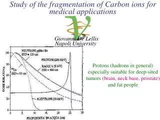
Hadrontherapy motivation • For hadrons (compared to X and γ): • Energy deposited at the end of ionization range • For 12C (compared to protons): • Reduced lateral and longitudinal diffusion; • Higher therapeutic effectiveness; • Tissue thickness tunable by changing the nuclei energy; • Less energy deposited to healthy neighboring tissues
Hadrontherapy Facilities in Europe: http://enlight.web.cern.ch/facilities
Patient Statistics (for facilities in operation at the end of 2012): http://enlight.web.cern.ch
Fragmentation of 12C • Nuclear fragments are generated during the interaction inside the tissue • Fragments have higher range and different direction with respect to primary ions • Precise knowledge of fragments is necessary to predict the detailed irradiation of the neighboring tissues and, thereby, optimization of the therapy with higher effectiveness • What we need to know 12C (400 MeV/n) on water Bragg-Peak • Kind of fragments • Which energy? • Which angle? Simulation: A. MairaniPhDThesis, 2007, Nuovo Cimento C, 31, 2008
Outline • Hadrontherapy motivation • The 12C fragmentation measurement with the Emulsion Cloud Chamber (ECC) detector • The FIRST detector • Measurements at GSI in the FIRST set-up • Preliminary results • Conclusion
Carbon exposure at HIMAC* (NIRS**- Chiba(Japan)) Emulsion Cloud Chamber (ECC) *Heavy Ion Medical Accelerator **National Institute of Radiological Sciences
The structure of the Emulsion Cloud Chamber • ECC structure: • “OPERA” type: alternate passive and sensitive material • High resolution tracking device: nuclear emulsion (300 µm thick) • Passive material: lexan plates 1 mm thick • 73 consecutive “cells”: 219 alternate nuclear and lexan layers • Lexan: =1.15 g/cm3 and electron density=3.6∙1023/cm3 (water: 3.3∙1023/cm3) Elementary cells 12C 300 μm EMULSION LAYER 1000 μm LEXAN LAYER
LEXAN LEXAN LEXAN The cell structure of the Emulsion Cloud Chamber R0 R1 R2 Emulsion were differently treated after the exposure and before the chemical treatment according to their position in the elementary cell (0,1,2) 12C 300 μm 1 mm • R0: • Not refreshed • Developed soon after the exposure • Sensitive to m.i.p. • R1: • 3 day refreshing at 98% relative humidity at 30°C • Insensitive to m.i.p. • Sensitive to protons • R2: • 3 day refreshing at 98% relative humidity at 38°C • Sensitive to He
50 μm Nuclear emulsion • Charged particle detector • First kind of detector for ionizing radiation • AgBrcrystal (0.2 μm) is the elementary detection cell • The particle tracking is registered from the AgBr grains along its path Microscope image 30-40 grains/100 μm per MIP
OPERA emulsions • OPERA industrial emulsions from FujiFilm • The AgBr density in the OPERA emulsions is higher in respect to the commercial films • Special R&D for OPERA: the double pouring procedure Plastic Base (205 microns) After refreshing ~1 tracks/mm^2 Before refreshing >30 tracks/mm^2 Emulsion Layer (43 microns) Emulsions are continuously sensitive detector ALL charged particle: cosmic rays, natural radioactivity etc recorded as a latent images. They can be partially erased by a “refreshing” procedure applied just before the detector assembling. 150 microns
Emulsion scanning system • Illumination system, objective (oil 50× NA0.85) and optical tube (Nikon) Z s t a ge ( M i c o s ) 0.05 µm no minal precisio n C M O S c a m e r a 1 2 8 0 × 1 0 2 4 p i xe l 2 5 6 gr a y l e v e l s 376 f r ames /s ec (Mikr o tr o n MC1310) X Y s t a ge ( M i c o s ) Em u lsi on Pla t e 0.1 µm no minal precisio n • OPERA expertise in scanning • 3d track reconstruction • Scanning speed: 20 cm2/h • Spatial resolution: ~0.3 m • • Angular resolution: ~2 mrad • • Detection efficiency of the tracks: ~95% 16
Principle of scanning emulsion 16 images taken through 44-micron emulsion layer
Automatic scanning system • Micro-track reconstruction in one emulsion layer by combining clusters belonging to images at different levels. • Micro-tacks are connected across the plastic base to form a base-tracks.
Results He Combining the information on consecutive films to get rid of the saturation effect R0 vs R1 and R1 vs R2 scatter plot H Journal of Instrumentation 2 (2007) P06004
Charge identification 4 cm thick chamber 2 cm thick chamber Z = 4 Z = 3 Z = 2 8 cm thick chamber 6 cm thick chamber Z = 6 Z = 5 Z = 4 Z = 3 Z = 2
Charge separation Journal of Instrumentation 2 (2007) P06004
Scattering angle of emitted particles Hydrogen Helium Lithium
Cross-section measurement • A volume of about 24 cm3 analyzed • Average energy of the Carbon beam: 315 MeV/n • Counting the events with Lithium (z = 3), Beryllium (z = 2) and Boron (z = 1) as the heaviest particle in the final state Black points: Phys.Rev.C75 (2007) 054606
8Be production Cross Section • 8Be He + He (10-16 s) • Q value 90 keV small opening angle • Opening angle between pairs of reconstructed Helium tracks One event p He C He Peak at 20≈mrad p
Outline • Hadrontherapy motivation • The 12C fragmentation measurement with the Emulsion Cloud Chamber (ECC) detector • The FIRST detector • Measurements at GSI in the FIRST set-up • Preliminary results • Conclusion
FIRST experiment • FIRST: Fragmentation of Ions Relevants for Space and Therapy • Aim: • Production yelds of Z=0, 1, 2 ,3 ,4 ,5 fragments • Measurement of cross section wrt angle and energy, with large angular acceptance • A collaborationamong: • INFN: Cagliari, LNF, LNS, Milano, Napoli, Roma3,Torino; • DSM/IRFU/SPhNCEA Saclay, IN2P3 Caen, Strasbourg, Lyon; • GSI: • Therapeuticalbeam of 12C @ 200-400 MeV/n available • Existing setup designed for higher E and Z fragments: Dipole magnet, Large Volume TPC, TOF Wall, low angle Neutron detector. • ESA, CERN
What do we expect from MC (FLUKA)? • The Z>2 produced fragments approximately have the same velocity of the 12C beam projectiles and are collimated in the forward direction • The protons are the most abundant fragments with a wide angular distribution and a kineticenergyspectrumup to 1 Gev/n • The Z=2 fragment are emitted within 20°of angular aperture Kinetic energy (MeV/nucl) Emission angle (deg)
FIRST set up The measurements were performed at the GSI facilities, where a therapeuticalbeam of 12C @ 200-400 MeV/n is available LAND Fragments Incident Beam ALADIN Bending magnet (<6°) VETO COUNTER Identifies particles coming from primary beam • KENTROS • Interaction region: • Start counter • Beam monitor • Vertex detector • Proton tagger 6° Target • MUSIC • Energy particles • Slope particles TIME OF FLY WALL
Outline • Hadrontherapy motivation • The 12C fragmentation measurement with the Emulsion Cloud Chamber (ECC) detector • The FIRST detector • Measurements at GSI in the FIRST set-up • Preliminary results • Conclusion
The FIRST set-up 10.2cm 12.5cm ECC ECC1 ECC2 ECC “FIRST experiment: Fragmentation of Ions Relevant for Space and Therapy” Journal of Physics: Conference Series 420 (2013) 012061 doi:10.1088/1742-6596/420/1/012061
Beamexposure of ECC • 12C beam with 400 MeV/n • Carbon target (8 mm thick) • Two ECC werecollocated inside the detector FIRST • Dedicated study on large angle track detection beam α2 a ≈ 16.5 cm α1 b ≈ 0.5 cm ECC2 ECC1 2°≤ α2 ≤ 38° 38°≤ α1≤ 57°
10.2cm 12.5cm ECC strucutre • ECC structure: • Not homogeneous structure • 6 consecutive emulsion films • 56 nuclear emulsion layers (300 m) interleaved with 56 lead plates (1 mm) film 62 6 consecutive emulsions film 57 film 56 1 mm leadlayer ECC 300 m nuclearemulsion film 2 film 1
Outline • Hadrontherapy motivation • The 12C fragmentation measurement • The Emulsion Cloud Chamber (ECC) detector • The FIRST detector • Measurements at GSI in the FIRST set-up • Preliminary results • Conclusion
ECC 2: Tracks angular distribution Signal and cosmic rays • 20 emulsions were scanned (6 consecutive emulsions and 14 emulsions interleaved with lead) • Data were scanned and processed up to tgq≤ 2 Signal cut: -0.9 ≤ tg Θx ≤ -0.1 -0.3 ≤ tg Θy ≤ 0.28) Signal is effectively measured at: 3°≤q≤ 40° (for ECC2) 40°≤q≤ 60° (for ECC1) as it was expected from the exposition geometry
Signal and cosmic ray range distribution • Tracks selected: • -0.9 ≤ tg Θx ≤ -0.1 • -0.3 ≤ tg Θy ≤ 0.28 • number of segments ≥ 2 Signal Cosmicrays preliminary results
Reconstruction efficiency Efficiency vs tracks slope Signal Cosmicrays Angular distribution of only signal corrected by efficiency CR/(S+CR)=24.4% preliminary results
Kinematical measurements1. Momentum measurement by multiple coulomb scattering (MCS) From the slope measurements along the particle track of the same particle obtained from the ECC it is possible to calculate the particle impulse in the range: 200 MeV/c ÷ 2 GeV/c 13.6 The algorithm was used for OPERA experiment and is based on: x p(MeV/c)= (mrad) X0 “Momentum measurement by the angular method in the Emulsion Cloud Chamber”, Nuclear Instruments and Methods in Physics Research A 512 (2003) 539–545
Kinematical measurements1.Momentum measurement by MCS • Tracks behind the first 6 emulsions • Tracks with at least 3 segments passing through 11 % of the total tracks of the sample preliminary results
Kinematical measurements2. Momentum measurement by range • Tracks for which it is not possible the measurement by the MCS method • Tracks stopped in the first 6 emulsions • Tracks not stopped inside the considered volume (20 layers) 82 % of the totaltracks of the sample preliminary results
Outline • Hadrontherapy motivation • The 12C fragmentation measurement with the Emulsion Cloud Chamber (ECC) detector • The FIRST detector • Measurements at GSI in the FIRST set-up • Preliminary results • Conclusion
Conclusions • Emulsion Cloud Chamber technique used to study the fragmentation of Carbon ions • Homogeneous ECC used as target and detector • Not Homogeneous ECC used as detector From these studies: • Discrimination of produced fragments in Z • Charge-changing cross-section measured • Moment measurement with MCS algorithm and range method
Reconstructionefficiency • Tracks selected: • angle selection • number of segments ≥ 2 • Number of plates≥ 6 Cosmicrays Signal -0.9≤ tg Θx ≤ -0.1 -0.3 ≤ tg Θy ≤ 0.28 0.1≤ tg Θx ≤ 0.9 -0.3 ≤ tg Θy ≤ 0.28)
Camera Image Processor board(Matrox Odyssey) Host PC(Dual PentiumWorkstation)RunningWinXP 2D Images(peak 452 MB/s,avg. 97 MB/s) Binarized2D Images Motors(VEXTA Nanostep) Motion Controller(National InstrumentsFlexMotion) 3Dmicrotracks XYZ MotionCommands Power Tomographic sequencesZ axis moving, 2D imagesspanning emulsion thickness 280×365μm2 Next field of view,Z at top, new cycle Process/save data Move XYZ to next view Data (images) processing and motion control flow in the ESS DAQ cycle(185 ms) Functional blocks
Cosmic-ray angular distribution • Films transported from Gran Sasso to CERN • Brick assembled at CERN • Cosmic-ray integrated during the transportation of the brick from CERN to GSI and from GSI to Gran Sasso • Brick disassembled and film developed at Gran Sasso Cosmic-rays taken with the films inside the brick in the same geometrical configuration as for the beam at GSI, with the brick rotated by 90 degrees to minimize the flux