Download
1 / 37
370 likes | 375 Views
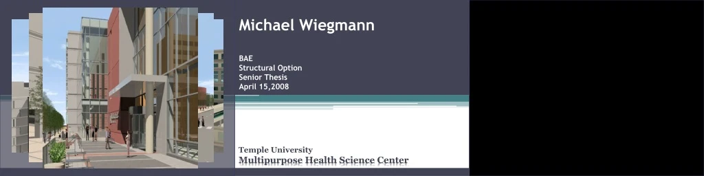
Michael Wiegmann. BAE Structural Option Senior Thesis April 15,2008. Temple University Multipurpose Health Science Center. Contents. Introduction Design Scenario Existing Structure Structural Redesign Architectural Redesign Conclusions.

E N D
Michael Wiegmann BAE Structural OptionSenior ThesisApril 15,2008 Temple University Multipurpose Health Science Center
Contents • Introduction • Design Scenario • Existing Structure • Structural Redesign • Architectural Redesign • Conclusions Introduction ∙ Design Scenario ∙ Existing ∙ Structural Redesign ∙ Architectural Redesign∙ Conclusions
Introduction – Project Overview • Multipurpose Health Science Center (MHSC) • Philadelphia, Pennsylvania • 480,000 SF, 13 stories • $150 million fast track • Medical research and education • Players • Owner: Temple University • Archit., Struct., MEP: Ballinger, Inc. • GC & CM: Gilbane, Inc. Introduction∙ Design Scenario ∙ Existing ∙ Structural Redesign ∙ Architectural Redesign∙ Conclusions
Design Scenario • Problem: • Tight urban location • Solution: • Vertical expansion • Criteria: • Architectural Redesign (discussed later) • Structural Redesign • Goals: • Meet design criteria (strength/serviceability/ capacity) • Maintain or exceed efficiency (weight ratio, SF use) • Minimal effect on architecture Introduction ∙ Design Scenario ∙ Existing ∙ Structural Redesign ∙ Architectural Redesign∙ Conclusions
Existing Structure Introduction ∙ Design Scenario ∙ Existing∙ Structural Redesign ∙ Architectural Redesign∙ Conclusions
Existing – Gravity System • Framing • Steel framing • Braced frames and moment frames • Typical framing areas • Typical bay 30’x30’ • Addition: areas 1, 2, 3, 4 • Decking • 2.5”, f’c=4,000 psi, NWC on 3”deep, 20 gage, galvanized composite steel deck, with 6x6-W2.9xW2.9 WWF • Beam & girder sizes • w18x40 to w24x76 • Vibration control Introduction ∙ Design Scenario ∙ Existing∙ Structural Redesign ∙ Architectural Redesign∙ Conclusions
Existing – Lateral System • Braced Frames • East-West • Resist: • 1525 kips wind (new: 2322 kips) • ASCE7-05 6.5 Analytical Procedure • 970 kips seismic (new: 960) • ASCE7-05 12.8.2 Equivalent Lateral Force Procedure • Moment Frames • North-South • Resist: • 506 kips wind (new: 714kips) • 970 kips seismic (new: 960) Introduction ∙ Design Scenario ∙ Existing∙ Structural Redesign ∙ Architectural Redesign∙ Conclusions
Existing – Foundations • 40% footings • 60% caissons • Up to Ø=8’ • terminate at bedrock, present at 30’ to 50’ depths • Soil bearing capacity • 60,000 psf • Soil • 19’to 35’: medium to very compact micaceous silty fines • 24’ to 50’, more compact micaceous silty fines terminating at intact mica bedrock Introduction ∙ Design Scenario ∙ Existing∙ Structural Redesign ∙ Architectural Redesign∙ Conclusions
Existing – Vibration Control • Previously mentioned sizes controlled by vibration design • Architectural programming • Labs, support areas, offices • Vibration control criteria: • Steel Design Guide Series 11: Floor Vibration Due to Human Activity • Design for Sensitive Equipment Introduction ∙ Design Scenario ∙ Existing∙ Structural Redesign ∙ Architectural Redesign∙ Conclusions
Existing – Vibration Control • Vibration analysis area: • Typical tower level laboratory • Procedure: • Determine floor properties • Movement due to walking • Compare with equipment velocity criteria Introduction ∙ Design Scenario ∙ Existing∙ Structural Redesign ∙ Architectural Redesign∙ Conclusions
Existing – Vibration Control • Transformed member properties: • Slab, joist, girder • Mid span flexibility • Panel deflection = 8.108x10⁻⁶ in • Expected maximum velocity • Maximum force Fm from Table 6.2 • Fast walking speed = 0.0311 in/s • Moderate walking speed = .0068 in/s • Slow walking speed = 0.0019 in/s Introduction ∙ Design Scenario ∙ Existing∙ Structural Redesign ∙ Architectural Redesign∙ Conclusions
Existing – Vibration Control • Results • Floor adequate for less sensitive equipment and procedures • Bench microscopes at magnification of 100x • Surgery, operating procedures • Redesign is necessary for more sensitive equipment types: • MRI equipment, Mass spectrometers, Cell implant equipment Introduction ∙ Design Scenario ∙ Existing∙ Structural Redesign ∙ Architectural Redesign∙ Conclusions
Structural Redesign Introduction ∙ Design Scenario ∙ Existing ∙ Structural Redesign ∙ Architectural Redesign∙ Conclusions
Structural Redesign – Goals • Focus on lateral system • Meet design criteria (strength/serviceability) • Maintain or exceed efficiency (weight ratio) • Redesign North-South moment frames as braced • Minimal effect on architecture Introduction ∙ Design Scenario ∙ Existing ∙ Structural Redesign ∙ Architectural Redesign∙ Conclusions
Structural Redesign – Frame Geometry • East-West braced frames • Maintain location • Chevron bracing to roof • Lower bracing: openings, doorways, etc Introduction ∙ Design Scenario ∙ Existing ∙ Structural Redesign ∙ Architectural Redesign∙ Conclusions
Structural Redesign – Frame Geometry • North - South braced frames • Quantity • Location selection • Minimal Architectural impact • Torsional issues • Eccentric chevron bracing to roof Introduction ∙ Design Scenario ∙ Existing ∙ Structural Redesign ∙ Architectural Redesign∙ Conclusions
Structural Redesign – Frame Modeling • RAM model • New vs. original design • Design input • Input geometry • Hand input loads • Strength design • RAM design: Gravity sizing • Start with hand selected trial brace sizing • Design for strength: • Bracing: axial load • Columns/beams: combined • Drift design • Drifts too high by 31% (Max ∆= H/400 = 8.83”) • Repetitive resizing: Little change, esp. E-W (too high by 5.3%) Introduction ∙ Design Scenario ∙ Existing ∙ Structural Redesign ∙ Architectural Redesign∙ Conclusions
Structural Redesign – STAAD Check • Drift check • Used typical E-W frame • Compared drift for: • RAM story shears (STAAD Model • Hand estimated story shears • Results • Verified RAM modeling results • Explanations: • Eccentricity • Suspicious of NS frames (sizing, column orientation) Introduction ∙ Design Scenario ∙ Existing ∙ Structural Redesign ∙ Architectural Redesign∙ Conclusions
Structural Redesign – Final Lateral • Test hypothesis • Drastically increase sizes • Correcting N-S drift, corrected E-W drift as well • Cause: column orientation/eccentricity • I decreases by 67% • N-S e = 10’ • E-W e = 12’ Introduction ∙ Design Scenario ∙ Existing ∙ Structural Redesign ∙ Architectural Redesign∙ Conclusions
Structural Redesign – Final Lateral • N-S Frames • Drift controls design • 8.64”< Max ∆= H/400 = 8.83” • Sizing • Bracing geometry: beams and columns • Column orientation: I decreases by 67% • Penthouse Mechanical • Increase Efficiency? • Bracing geometry • Column orientation • Add frames • Penthouse Mechanical N-S Final Model Introduction ∙ Design Scenario ∙ Existing ∙ Structural Redesign ∙ Architectural Redesign∙ Conclusions
Structural Redesign – Final Lateral • E-W Frames • Were effected by N-S frame inefficiency • Drift controls design • 6.79”< Max ∆= H/400 = 8.83” E-W Model 37 E-W Final Model Introduction ∙ Design Scenario ∙ Existing ∙ Structural Redesign ∙ Architectural Redesign∙ Conclusions
Structural Redesign – Final Checks • RAM strength check • Extra capacity (drift control) • Column line check • Compares original and new RAM models with existing design • Very close results • Column comparison check • Compares original and new RAM models • Column size increase, except: • New braced frame columns greatly increased • Old moment frame columns decreased Introduction ∙ Design Scenario ∙ Existing ∙ Structural Redesign ∙ Architectural Redesign∙ Conclusions
Structural Redesign – Foundation • Caisson sizing • Obtain rough sizing estimate • Bearing capacity: 60,000 psf • Take all loading into account • Results • Most Ø = 8’ originally • Increase Ø to 9’ to 12’ (12%-52%) Introduction ∙ Design Scenario ∙ Existing ∙ Structural Redesign ∙ Architectural Redesign∙ Conclusions
Structural Redesign – Economy • Economic Analysis: New vs Original • Unit weight: ratio of steel weight to floor area • Compare unit weight % decrease • Separated into: • Lateral, Gravity Beam, Gravity Column • Conclusions: • Vertical expansion is feasible means for increasing program • Converting moment frames to braced increases efficiency • Despite over-sizing • Note: cost of moment connections Introduction ∙ Design Scenario ∙ Existing ∙ Structural Redesign ∙ Architectural Redesign∙ Conclusions
Structural Redesign – Conclusions • Vertical expansion • Feasible means for increasing program • Converting moment frames to braced • Minimized negative architectural impact • Further efficiency • Add another set of N-S braced frames • Change column orientation: deeper column Introduction ∙ Design Scenario ∙ Existing ∙ Structural Redesign ∙ Architectural Redesign∙ Conclusions
Architectural Redesign Introduction ∙ Design Scenario ∙ Existing ∙ Structural Redesign ∙ Architectural Redesign ∙ Conclusions
Architectural Redesign - Massing • Size & Scale • Medical Campus • Residential neighborhood Introduction ∙ Design Scenario ∙ Existing ∙ Structural Redesign ∙ Architectural Redesign ∙ Conclusions
Architectural Redesign - Massing • Size & Scale • Medical Campus • Residential neighborhood • Design Philosophy • Expression of interior functions on exterior Introduction ∙ Design Scenario ∙ Existing ∙ Structural Redesign ∙ Architectural Redesign ∙ Conclusions
Architectural Redesign - Massing • Size & Scale • Medical Campus • Residential neighborhood • Design Philosophy • Expression of interior functions on exterior • Square footage • Approx. 100,000 SF addition • 5 floors • 25,200 SF per floor • Final Massing • Takes all factors into account Introduction ∙ Design Scenario ∙ Existing ∙ Structural Redesign ∙ Architectural Redesign ∙ Conclusions
Architectural Redesign - Efficiency • Square footage efficiency: 80% • Original tower floor-plan • 28000 SF - 4260 SF corridor • 85% efficiency • New tower floor plan • 25200 SF - 4260 SF corridor • 83% efficiency Introduction ∙ Design Scenario ∙ Existing ∙ Structural Redesign ∙ Architectural Redesign ∙ Conclusions
Architectural Redesign – Green Space • Limited green space • Green roof addition • Intensive green roof – 1400 SF - library roof • Rooftop garden • Extensive green roof – 4800 SF - elsewhere • Higher “R-value” (thermal mass) • Cleaner runoff • Reduced runoff volume • Cost analysis – library area • Existing built-up roof = $3,990 • Extensive green roof = $39,400 • Intensive green roof = $49,870 • Conclusion: • Intensive green roof is 0.03% of $150 million budget Introduction ∙ Design Scenario ∙ Existing ∙ Structural Redesign ∙ Architectural Redesign ∙ Conclusions
Architectural Redesign - Egress • Occupancy • Business/Assembly occupancy • Adding 252 occupants/floor • 100SF/occupant, 25,200SF • Capacity • Exit widths: controlled by 1285 occupancy of library and auditorium • # of stairways: 2 Introduction ∙ Design Scenario ∙ Existing ∙ Structural Redesign ∙ Architectural Redesign ∙ Conclusions
Conclusions • Goals • Meet design criteria (strength/serviceability/ capacity) • Maintain or exceed efficiency (weight ratio, SF use) • Minimal effect on architecture • Structural Redesign • Vertical expansion: Feasible means for increasing program • Minimized negative architectural impact • Converting moment frames to braced: Increased efficiency • Further efficiency: Add frames/column orientation • Architectural Redesign • Massing • Maintain floor plan efficiency (83%) • Created green-space • Egress requirements met Introduction ∙ Design Scenario ∙ Existing ∙ Structural Redesign ∙ Architectural Redesign ∙ Conclusions
Acknowledgments Ballinger, Inc. Edward Zinski Scott Holsinger Joyce Raybuck Penn State Dr. Linda Hanagan M. Kevin Parfitt Robert J. Holland The entire AE faculty, staff, and students Temple University
Construction photos and full architectural renderings of original design taken from the following websites: • http://www.temple.edu/medicine/ • http://www.ballinger-ae.com