Download
1 / 35
350 likes | 359 Views
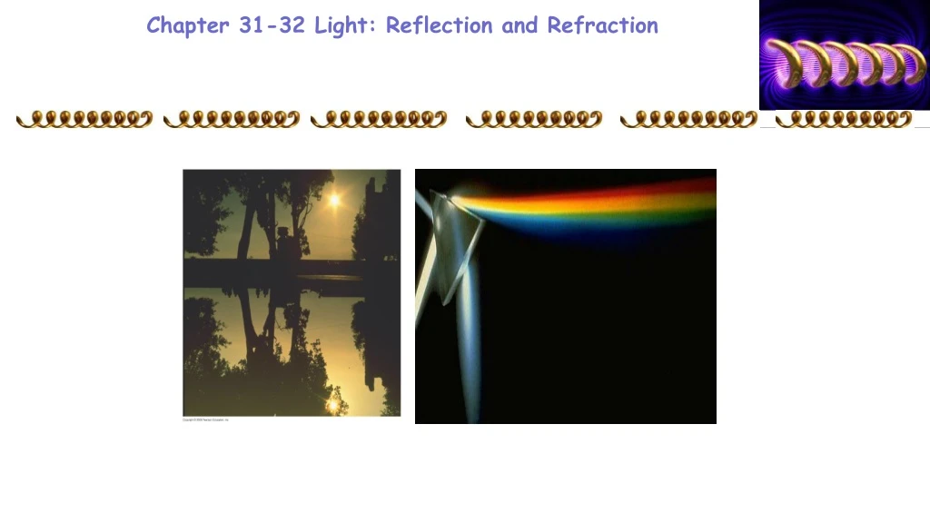
Chapter 31-32 Light: Reflection and Refraction. 29-3 EMF Induced in a Moving Conductor. Example 29-8: Force on the rod.

E N D
29-3 EMF Induced in a Moving Conductor Example 29-8: Force on the rod. To make the rod move to the right at speed v, you need to apply an external force on the rod to the right. (a) Explain and determine the magnitude of the required force. (b) What external power is needed to move the rod?
29-4 Electric Generators A generator is the opposite of a motor – it transforms mechanical energy into electrical energy. This is an ac generator: The axle is rotated by an external force such as falling water or steam. The brushes are in constant electrical contact with the slip rings.
29-4 Electric Generators If the loop is rotating with constant angular velocity ω, the induced emf is sinusoidal: For a coil of N loops,
29-6 Transformers and Transmission of Power A transformer is a device for increasing or decreasing an ac voltage A transformer consists of two coils, either interwoven or linked by an iron core. A changing emf in one induces an emf in the other. The ratio of the emfs is equal to the ratio of the number of turns in each coil: This is the transformer equation p: Primary s: Secondary
29-6 Transformers and Transmission of Power • It is designed so that all the current produced by the magnetic flux is in the primary coil. • This is a step-up transformer – the emf in the secondary coil is larger than the emf in the primary and Ns> Np
29-6 Transformers and Transmission of Power Energy must be conserved; therefore, in the absence of losses, the ratio of the currents must be the inverse of the ratio of turns: Because of conservation of energy, the power output cannot be greater than the power input
29-6 Transformers and Transmission of Power Example 29-12: Cell phone charger. The charger for a cell phone contains a transformer that reduces 120-V ac to 5.0-V ac to charge the 3.7-V battery. (It also contains diodes to change the 5.0-V ac to 5.0-V dc.) Suppose the secondary coil contains 30 turns and the charger supplies 700 mA. Calculate (a) the number of turns in the primary coil, (b) the current in the primary, and (c) the power transformed.
29-6 Transformers and Transmission of Power Transformers work only if the current is changing; this is one reason why electricity is transmitted as ac.
29-7 A Changing Magnetic Flux Produces an Electric Field . A changing magnetic flux induces an electric field;this is a generalization of Faraday’s law.The electric field will exist regardless of whether there are any conductors around:
30-1 Mutual Inductance Mutual inductance: a changing current in one coil will induce an emf in a second coil (flux due to current of the first coil) And vice versa; note that the constant M (the mutual inductance) depends on the size, shape and the number of turns, and is known as the mutual inductance, is the same:
30-1 Mutual Inductance Unit of inductance: the henry, H: 1 H = 1 V·s/A = 1 Ω·s. M12=M21 =M A transformer is an example of mutual inductance.
30-2 Self-Inductance A changing current in a coil will also induce an emf in itself: Here, L is called the self-inductance:
31-3 Maxwell’s Equations This set of equations describe electric and magnetic fields, and is called Maxwell’s equations. In the absence of dielectric or magnetic materials, they are: Gauss’s Law Gauss’s Law of magnetism A magnetic field induces a electric field General form of Ampere’s law An electric field induces a magnetic field
31-4 Production of Electromagnetic Waves Since a changing electric field produces a magnetic field, and a changing magnetic field produces an electric field, once sinusoidal fields are created they can propagate on their own. These propagating fields are called electromagnetic waves (EM).
Induced Electric Fields Changing B induces emf changing E Changing E changing B The oscillations (change) of the electric and magnetic fields create electromagnetic waves Electric & Magnetic fields induce each other
What is Light? https://www.youtube.com/watch?v=IXxZRZxafEQ
. 31-5 Electromagnetic Waves, and Their Speed, Derived from Maxwell’s Equations B and E are related by the following equation Calculated by Maxwell Here, v is the velocity of the wave. The magnitude of this velocity is around 3.0 x 10⁸ m/s – precisely equal to the measured speed of light. Maxwell’s argue that light is EM wave, Hertz confirmed Maxwell calculations experimentally 8 years later.
EM waves do not require a medium to propagate Speed of EM Waves -- vacuum Permittivity of free space = 8.85 x 10⁻¹² C2/Nm2 Permeability of free space: = 4 x 10⁻⁷ Tm/A
31-6 Light as an Electromagnetic Wave and the Electromagnetic Spectrum The frequency of an electromagnetic wave is related to its wavelength and to the speed of light:
Generally light slows down when it encounters a medium other than vacuum. Speed of Light in matter n is the index of refraction of the medium n≥1 lo l lo v c n Frequency is unchanged
31-6 Light as an Electromagnetic Wave and the Electromagnetic Spectrum Electromagnetic waves can have any wavelength; we have given different names to different parts of the wavelength spectrum.
32-1 The Ray Model of Light Light very often travels in straight lines. We represent light using rays, which are straight lines emanating from an object. This is an idealization, but is very useful for geometric optics.
32-2 Reflection; Image Formation by a Plane Mirror Law of reflection: the angle of reflection (that the ray makes with the normal to a surface) equals the angle of incidence.
32-2 Reflection; Image Formation by a Plane Mirror When light reflects from a rough surface, the law of reflection still holds, but the angle of incidence varies. This is called diffuse reflection. With diffuse reflection, your eye sees reflected light at all angles. With specular reflection (from a mirror), your eye must be in the correct position.
32-2 Reflection; Image Formation by a Plane Mirror What you see when you look into a plane (flat) mirror is an image, which appears to be behind the mirror.
32-2 Reflection; Image Formation by a Plane Mirror This is called a virtual image, as the light does not go through it. The distance of the image from the mirror di is equal to the distance of the object from the mirror d0
32-2 Reflection; Image Formation by a Plane Mirror Example 32-1: Reflection from flat mirrors. Two flat mirrors are perpendicular to each other. An incoming beam of light makes an angle of 15° with the first mirror as shown. What angle will the outgoing beam make with the second mirror?
32-3 Formation of Images by Spherical Mirrors Spherical mirrors are shaped like sections of a sphere, and may be reflective on either the inside (concave) or outside (convex).
Convex Spherical Mirrors Concave Like you are in a cave
32-3 Formation of Images by Spherical Mirrors Rays coming from a faraway object are effectively parallel.
32-3 Formation of Images by Spherical Mirrors Parallel rays striking a spherical mirror do not all converge at exactly the same place if the curvature of the mirror is large; this is called spherical aberration.
32-3 Formation of Images by Spherical Mirrors If the curvature is small, the focus is much more precise; the focal point is where the rays converge. Center of curvature: :Focal point :Focal length f=r/2 Radius of curvature
image Spherical Mirrors: Concave • Parallel ray goes through f • Ray through center reflects back • Ray through f comes out parallel object f C Image: Upright or upside down Real or virtual Bigger or smaller
image Spherical Mirrors: Convex Radius of Curvature R Center of Curvature object C f Principle axis Focal point f=R/2 Image: Upright or upside down Real or virtual Bigger or smaller • Parallel ray goes through f • Ray through center reflects back • Ray through f comes out parallel