Download
1 / 14
190 likes | 386 Views
Foremost, I would like to express my sincere gratitude to my advisor prof. Nisha Dhiman (Roorkee College of Engineering) for the continuous support of my Project Orientation Program, for her patience, motivation, enthusiasm, and immense knowledge.Her guidance helped me in all the time of research and writing of this thesis. I could not have imagined having a better advisor and mentor for my POP.

E N D
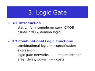
NOT GATE (INVERTER GATE) BY MONISH ANSARI B.TECH ELECTRICAL AND ELECTRONICS ENGINEERING ROORKEE COLLEGE OF ENGINEERING ROORKEE-247667
TABLE OF CONTENT ACKNOWLEDGEMENT ABSTRACT INTRODUCTION THEORY IMPLEMENTATION BIBLIOGRAPHY
ACKNOWLEDGEMENT Foremost, I would like to express my sincere gratitude to my advisor prof. Nisha Dhiman for the continuous support of my Project Orientation Program, for her patience, motivation, enthusiasm, and immense knowledge. Her guidance helped me in all the time of research and writing of this thesis. I could not have imagined having a better advisor and mentor for my POP. Besides my advisor, I would like to thank the rest of my thesis committee:Prof. Ishampal Chandra,Prof.Priyanka Rana , for their encouragement, insightful comments, and hard questions. My sincere thanks also goes to Dr. Sangram Bana for offering me the opportunities and leading me working on diverse exciting projects. I thank my fellow labmates in Roorkee College of engineering,Prince Sharma and Satya Narayan Rai for the stimulating discussions, for the sleepless nights we were working together before deadlines, and for all the fun we have had in the last few days.I am grateful to prof. Shubham Sharma for enlightening me the first glance of research. I would also like to thank my college ROORKEE COLLEGE OF ENGINEERING for providing me a platform to show my talent and hardworks to others,and give my best to my country. Last but not the least, I would like to thank my family: my parents Meena and Khursheed Ali for giving birth to me at the first place and supporting me spiritually throughout my life.
ABSTRACT In digital logic, an inverter or NOT gate is a logic gate which implements logical negation. The truth table is shown on the right. An inverter circuit outputs a voltage representing the opposite logic-level to its input. Its main function is to invert the input signal applied. If the applied input is low then the output becomes high and vice versa. Inverters can be constructed using a single NMOS transistor or a single PMOS transistor coupled with a resistor. Since this 'resistive-drain' approach uses only a single type of transistor, it can be fabricated at low cost. However, because current flows through the resistor in one of the two states, the resistive-drain configuration is disadvantaged for power consumption and processing speed. Alternatively, inverters can be constructed using two complementary transistors in a CMOS configuration. This configuration greatly reduces power consumption since one of the transistors is always off in both logic states. Processing speed can also be
improved due to the relatively low resistance compared to the NMOS-only or PMOS-only type devices. Inverters can also be constructed with bipolar junction transistors (BJT) in either a resistor–transistor logic (RTL) or a transistor–transistor logic (TTL) configuration. Digital electronics circuits operate at fixed voltage levels corresponding to a logical 0 or 1 (see binary). An inverter circuit serves as the basic logic gate to swap between those two voltage levels. Implementation determines the actual voltage, but common levels include (0, +5V) for TTL circuits.
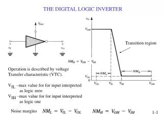
INTRODUCTION Logic gates are the basic building blocks of digital logic circuits as well as digital electronics. A gate is defined as a logic device which computes functionally on a 2 valued input signal. Logic gates are of many types such as OR, AND, NOR, NAND, EX –OR and NOT etc. Among these, all gates have two inputs and one output except NOT gate. NOT gate has only one input and one output. This gate produces the reverse output of applied input. So this gate is also called as ‘Digital Inverter’. NOT Gate Logic Symbol and Boolean Expression We know the NOT gate is an inverter, which inverts or reverses the input.. So the output is represented by ‘-’ bar symbol of the input. The Boolean expression of the NOT gate is Z =X ̅. Pronounced as “Z is equal to X bar”. The logic symbol of the NOT gate is shown in below figure. If X is the input and Z is the output, then if X = 0, then Z = 1 If X = 1, then Z = 0.
The bubble at the output port represents the inverting operation. That means for high logic signal input, the output of the NOT gate will be LOW, similarly for low logic signal input the output of NOT gate will be HIGH. We can easily understand this by truth table stated below.
THEORY Explanation of Not gate with light switch circuit The NOT gate can be easily understood by using a LED (light emitted Diode) circuit. This is also called Light switch circuit. In this circuit, NOT gate functions like an electronic switch. When it got high input, the LED connected at the output will be OFF, as the output of NOT gate becomes 0. In the same way, when the logic gate is connected with LOW input, the LED will be ON, as the output becomes 1. The Light switching circuit with NOT gate is shown below.
Here we connect an alterable switch with the NOT gate and the output of NOT gate is connected to a LED. An LED is an electronic device which will ON and off when it receives high voltage and low voltage respectively. When the switch is connected to +5 V, the switch is on position so the LED emits light. When the NOT gate is connected to Ground, the LED will OFF so it doesn’t emit any light. Pulsed Operation When we apply a pulse signal to the NOT gate, it will ON and OFF for HIGH and LOW levels respectively. This means,
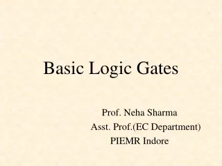
Not Gate using NPN Transistor We can design a NOT gate by using a NPN transistor as shown in below picture. The Base (B) of the NPN transistor is connected with the input signal X. we connect a supply voltage of +5 V to the emitter (E) and the output Z is collected at the emitter. When the low level voltage 0 V is connected to the input, then the transistor will be OFF. So no current flows through it. This means the supply voltage +5 V will be measured at the output port, which is considered as HIGH state Similarly, when the high level voltage +5 V is connected to the input, then the transistor will be ON. So the total supply current will be drawn by transistor. This means the no voltage is measured at the output port, which is considered as LOW state. At this situation the output voltage is measured as +5 V, which will be considered as HIGH logic level. The transistor designed NOT gate is shown below.
IMPLEMENTATION Objective – To implement the logic NOT gate using NPN transistor Components Required – 1. A breadboard 2. A bunch of 5k and 10k resistors 3. A LED 4. Any NPN type transistors (for example 2N3904, BC547, BC548, BC549 etc.) 5. Supply source 6. Voltage regulation IC 7805 if you are using 9 volt battery source. 7. Switches Circuit Details:-
Concept about NOT GATE :- It is a single input device which has an output level that is normally at logic level “1” and goes “LOW” to a logic level “0” when its single input is at logic level “1”, in other words it “inverts” (complements) its input signal. The output from a NOT gate only returns “HIGH” again when its input is at logic level “0” giving us the Boolean expression of:A = Q. Then we can define the operation of a single input digital logic NOT gate as being: “If A is NOT true, then Q is true” TRANSISTOR NOT GATE – A simple 2-input logic NOT gate can be constructed using a RTL Resistor- transistor switches as shown below with the input connected directly to the transistor base. The transistor must be saturated “ON” for an inverted output “OFF” at Q.
Logic NOT Gates are available using digital circuits to produce the desired logical function. The standard NOT gate is given a symbol whose shape is of a triangle pointing to the right with a circle at its end. This circle is known as an “inversion bubble” and is used in NOT, NAND and NOR symbols at their output to represent the logical operation of the NOT function. This bubble denotes a signal inversion (complementation) of the signal and can be present on either or both the output and/or the input terminals.
BIBLIOGRAPHY PROF.NISHA DHIMAN (ECE DEPT.) ROORKEE COLLEGE OF ENGINEERING. PROF.ISHAMPAL CHANDRA (ECE DEPT.) ROORKEE COLLEGE OF ENGINEERING. PROF.PRIYANKA RANA (ECE DEPT.) ROORKEE COLLEGE OF ENGINEERING. www.electronicshub.com www.electrical4u.com www.wikipedia.com www.tutorialspoint.com INTEGRATED ELECTRONICS ANALOG AND DIGITAL SYSTEM-JACOM MILLIMAN. CHRISTOS C.HALKIAS. ELECTRONIC DEVICES AND CIRCUIT THEORY-ROBERT L.BOYLSTAD LOUIS NASHELSKY.