Download

1 / 86
990 likes | 1.38k Views
Heat Exchanger Design. Anand V P Gurumoorthy Associate Professor Chemical Engineering Division School of Mechanical & Building Sciences VIT University Vellore, India. Heat Exchanger Classification. Recuperative:

E N D
Heat Exchanger Design Anand V P Gurumoorthy Associate Professor Chemical Engineering Division School of Mechanical & Building Sciences VIT University Vellore, India
Heat Exchanger Classification • Recuperative: • Cold and hot fluid flow through the unit without mixing with each other. The transfer of heat occurs through the metal wall. • Regenerative: • Same heating surface is alternately exposed to hot and cold fluid. Heat from hot fluid is stored by packings or solids; this heat is passed over to the cold fluid. • Direct contact: • Hot and cold fluids are in direct contact and mixing occurs among them; mass transfer and heat transfer occur simultaneously.
Heat Exchanger Standards and Codes • British Standard BS-3274 • TEMA standards are universally used. • TEMA standards cover following classes of exchangers: • Class R – designates severe requirements of petroleum and other related processing applications • Class C – moderate requirements of commercial and general process applications • Class B – specifies design and fabrication for chemical process service.
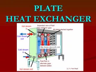
Shell and Tube Heat Exchanger • Most commonly used type of heat transfer equipment in the chemical and allied industries. • Advantages: • The configuration gives a large surface area in a small volume. • Good mechanical layout: a good shape for pressure operation. • Uses well-established fabrication techniques. • Can be constructed from a wide range of materials. • Easily cleaned. • Well established design procedures.
Types of Shell and Tube Heat Exchangers • Fixed tube design • Simplest and cheapest type. • Tube bundle cannot be removed for cleaning. • No provision for differential expansion of shell and tubes. • Use of this type limited to temperature difference upto 800C. • Floating head design • More versatile than fixed head exchangers. • Suitable for higher temperature differentials. • Bundles can be removed and cleaned (fouling liquids)
Design of Shell and Tube Heat Exchangers • Kern method: • Does not take into account bypass and leakage streams. • Simple to apply and accurate enough for preliminary design calculations. • Restricted to a fixed baffle cut (25%). • Bell-Delaware method • Most widely used. • Takes into account: • Leakage through the gaps between tubes and baffles and the baffles and shell. • Bypassing of flow around the gap between tube bundle and shell. • Stream Analysis method (by Tinker) • More rigorous and generic. • Best suited for computer calculations; basis for most commercial computer codes.
Construction Details – Tube Dimensions • Tube diameters in the range 5/8 inch (16 mm) to 2 inch (50 mm). • Smaller diameters (5/8 to 1 inch) preferred since this gives compact and cheap heat exchangers. • Larger tubes for heavily fouling fluids. • Steel tubes – BS 3606; Other tubes – BS 3274. • Preferred tube lengths are 6 ft, 8 ft, 12 ft, 16 ft, 20 ft and 24 ft; optimum tube length to shell diameter ratio ~ 5 – 10. • ¾ in (19 mm) is a good starting trial tube diameter.
Construction Details – Tube Arrangements • Tubes usually arranged in equilateral triangular, square or rotated square patterns. • Tube pitch, Pt, is 1.25 times OD.
Construction Details - Shells • Shell should be a close fit to the tube bundle to reduce bypassing. • Shell-bundle clearance will depend on type of heat exchanger.
Construction Details – Tube Count • Bundle diameter depends not only on number of tubes but also number of tube passes. • Nt is the number of tubes • Db is the bundle diameter (mm) • D0 is tube outside diameter (mm) • n1 and K1 are constants
Construction Details - Baffles • Baffles are used: • To direct the fluid stream across the tubes • To increase the fluid velocity • To improve the rate of transfer • Most commonly used baffle is the single segmental baffle. • Optimal baffle cut ~ 20-25%
Basic Design Procedure • General equation for heat transfer is: where Q is the rate of heat transfer (duty), U is the overall heat transfer coefficient, A is the area for heat transfer ΔTm is the mean temperature difference • We are not doing a mechanical design, only a thermal design.
Overall Heat Transfer Coefficient • Overall coefficient given by: h0 (hi) is outside (inside) film coefficient hod (hid) is outside (inside) dirt coefficient kw is the tube wall conductivity do (di) is outside (inside) tube diameters
Individual Film Coefficients • Magnitude of individual coefficients will depend on: • Nature of transfer processes (conduction, convection, radiation, etc.) • Physical properties of fluids • Fluid flow rates • Physical layout of heat transfer surface • Physical layout cannot be determined until area is known; hence design is a trial-and-error procedure.
Fouling Factors (Dirt Coeffs) • Difficult to predict and usually based on past experience
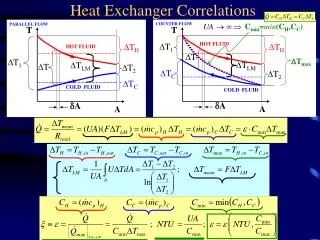
Mean Temperature Difference (Temperature Driving Force) • To determine A, ΔTm must be estimated • True counter-current flow – “logarithmic temperature difference” (LMTD)
LMTD • LMTD is given by: where T1 is the hot fluid temperature, inlet T2 is the hot fluid temperature, outlet t1 is the cold fluid temperature, inlet t2 is the cold fluid temperature, outlet
True Temperature Difference • Obtained from LMTD using a correction factor: ΔTm is the true temperature difference Ft is the correction factor • Ft is related to two dimensionless ratios:
Temp Correction Factor Ft Temperature correction factor, one shell pass, two or more even tube passes
Fluid Allocation: Shell or Tubes? • Corrosion • Fouling • Fluid temperatures • Operating pressures • Pressure drop • Viscosity • Stream flow rates
Shell and Tube Fluid Velocities • High velocities give high heat-transfer coefficients but also high pressure drop. • Velocity must be high enough to prevent settling of solids, but not so high as to cause erosion. • High velocities will reduce fouling • For liquids, the velocities should be as follows: • Tube side: Process liquid 1-2m/s Maximum 4m/s if required to reduce fouling Water 1.5 – 2.5 m/s • Shell side: 0.3 – 1 m/s
Pressure Drop • As the process fluids move through the heat exchanger there is associated pressure drop. • For liquids: viscosity < 1mNs/m2 35kN/m2 Viscosity 1 – 10 mNs/m2 50-70kN/m2
Tube-side Heat Transfer Coefficient • For turbulent flow inside conduits of uniform cross-section, Sieder-Tate equation is applicable: C=0.021 for gases =0.023 for low viscosity liquids =0.027 for viscous liquids μ= fluid viscosity at bulk fluid temperature μw=fluid viscosity at the wall
Tube-side Heat Transfer Coefficient • Butterworth equation: • For laminar flow (Re<2000): • If Nu given by above equation is less than 3.5, it should be taken as 3.5
Heat Transfer Factor, jh • “j” factor similar to friction factor used for pressure drop: • This equation is valid for both laminar and turbulent flows.
Heat Transfer Coefficients for Water • Many equations for hi have developed specifically for water. One such equation is: where hi is the inside coefficient (W/m2 0C) t is the water temperature (0C) ut is water velocity (m/s) dt is tube inside diameter (mm)
Tube-side Pressure Drop where ΔP is tube-side pressure drop (N/m2) Np is number of tube-side passes ut is tube-side velocity (m/s) L is the length of one tube m is 0.25 for laminar and 0.14 for turbulent jf is dimensionless friction factor for heat exchanger tubes
Shell-side Heat Transfer and Pressure Drop • Kern’s method • Bell’s method
Procedure for Kern’s Method • Calculate area for cross-flow As for the hypothetical row of tubes in the shell equator. pt is the tube pitch d0 is the tube outside diameter Ds is the shell inside diameter lB is the baffle spacing, m. • Calculate shell-side mass velocity Gs and linear velocity, us. where Ws is the fluid mass flow rate in the shell in kg/s
Procedure for Kern’s Method • Calculate the shell side equivalent diameter (hydraulic diameter). • For a square pitch arrangement: • For a triangular pitch arrangement
Shell-side Reynolds Number • The shell-side Reynolds number is given by: • The coefficient hs is given by: where jh is given by the following chart
Shell-side Pressure Drop • The shell-side pressure drop is given by: where jf is the friction factor given by following chart.
(Figure 4 in notes) (Figure 2)
(Table 3 in notes) (Figure 10 in notes)