Download
1 / 21
220 likes | 524 Views
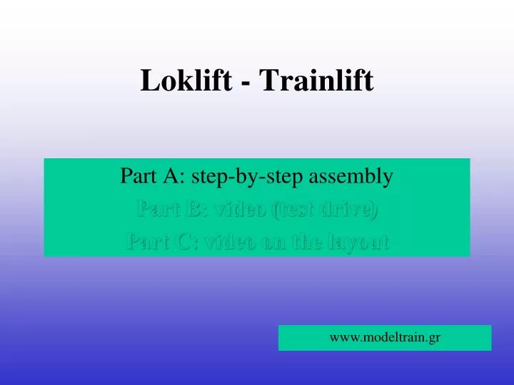
Loklift - Trainlift. Part A: step-by-step assembly Part B: video ( test drive ) Part C: video on the layout. www.modeltrain.gr. Loklift - Trainlift. What is Loklift ?

E N D
Loklift - Trainlift Part A:step-by-step assembly Part B:video (test drive) Part C:video on the layout www.modeltrain.gr
Loklift - Trainlift What is Loklift? It is a “garage” for trains, where the parking takes place in a seven-storey space. Each storey moves up and down. The system can be used as an exhibition window for locomotives and wagons. This gives solutions to space saving because it does not requireunderground parking (Rangierbahnhof). History: The idea of an elevator is not new. Many such ideas and constructionshave been implemented in the Internetand demonstrated in youtube.One can buy or construct this parking system. The assembly requires the involvement of two persons and it is relatively easy. Thewww. modeltrain.gr made this purchase in September 2010 from the German firm MUET Digirail Dachau. Technical specifications: The system consists primarily of two mechanical parts,one rectangular aluminum frame as the support base on the ground and one vertical frame on which the seven floors are supported and move. Each floor (level) has tree H0-tracks with length of 120cm and width of 15cm. The storey control is accomplished electronically via PCand suitable software.
Frame base The frame is supported on 4 rubber bases
Assembly of columns Two vertical columns are fixed with screws onto the frame base…
Loose support of columns ….. and are screwed – are loosely supported crosswise
Placement on the axle Adaptation on the axle ……
Placement on the axle Placement up to the axle pin……
Placement of toothed wheel’s axle Placement of toothed wheel’s axle with chain on the other edge of the axle
Placement of axle on column The axle is placed carefully between the columns….
Chain alignment …as long as the chain has been firstly aligned,so that the white spot is here… (it is required for the correct operation of the mechanism)
Fixation of motor The motor along with its base are screwed firmly on the column
Fixation of columns ….. The columns are screwed now firmly …..
Contacts for electrical connections with the levels Final outcome Special basefor support of levels (moves with chain) The box with the electronics is fixed on the right column by default Inputs – outputsof control wires
Lateral support of column We use an angle for stability of the columns
Level support There are 7 levels. Each level is screwed on own base.
Right sector of tracks (RST) Left sector of tracks (LST) Track pattern at every level
Dip switchesfor level recognition Contacts for power supply and sensors Electrical contact points Power supply strips Marklin C sensors B R Sector of train sensors (RST) (LST)
Electrical contact points Power supply R LED OFF No power supply to tracks Power supply B Position sensors LED ON Power supply to tracks
Level assembly Gap of 2-3 mmbetween levels and firm diorama