Download
1 / 21
210 likes | 335 Views
Multichannel readout system of inner tracker for NICA-MPD. Rogov Victor AFI, JINR , Dubna Afi.jinr.ru. Short data about NICA/MPD. Sh ort data about Inner Tracker. Afi.jinr.ru. The work purpose.

E N D
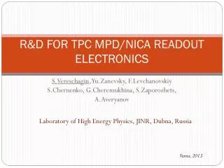
Multichannel readout system of inner tracker for NICA-MPD Rogov Victor AFI, JINR, Dubna Afi.jinr.ru
Short data about Inner Tracker Afi.jinr.ru
The work purpose • The development of a prototype of front-end-electronics for readout information from CBM01-B2 board Afi.jinr.ru
Collaboration • Scientific Research Technological Institute of Instrument Engineering (SE SRTIIE Ukraine) • Helmholtz Centre for Heavy Ion Research (GSI Germany) • Joint institute for nuclear research (JINR Russia)
Problems • The analysis of the existing multichannel chargesensetive preamplifiers for experiments of physics (JINR); • The analysis of main principles and methods of development of chips-adapters for open-frame installation of multichannel preamplifiers (JINR- SE SRTIIE); • Research of technological parameters, development and manufacture of chip-adapter (SE SRTIIE); • PCB layout development (JINR); • Assemblingand testing sample modules of front-end-electronics (JINR); Afi.jinr.ru
The base readout system Afi.jinr.ru
The sensor board СВМ01В2 Afi.jinr.ru
Key Features • mixed signal chip, 128 channels,1 test channel with analogue diagnostic output, available for positive and negative signals • self triggered, data driven de-randomizing, readout at 32 MHz • digital time stamp output, analogue peak hight output • analogue pile-up registry, programmable dead time, local threshold adjustment, dynamic Range: 120000 e • Shaping time and noise performance: • 18 ns fast shaper at 30 pF input, 850 enc for positive signals, 1000 enc for negative signals • 140 ns slow shaper at 30 pF input, 600 enc • Timing resolution ~ 2-3 ns, time stamp resolution 1 ns Afi.jinr.ru
The problems of existing FEB’s -three layer pads -small pitch of pads – 50 uM -A considerable quantity of bonding points - Low mechanical durability -Possibility of short circuit of donding conductors Afi.jinr.ru
The offered solutions • For decrease in probability of short circuit at bonding point’s, augmentations of a conductors pitch, total reduction of bonding point’s on PCB, augmentations of mechanical strength, a possibility of testing n-Xyter before bonding on pcb, suggestedto develop the chip-adapter, which: • Increases pitch of tab bonding point’s with 100 to 300 microns for entrance pad’s, and 100 microns to 400 for out pad’s; • Provides installation of the chip-adapter with a microcircuit at one layer of PCB. Afi.jinr.ru
TAB Bonding point’s of chip-adapter with PCB Chip-cable Afi.jinr.ru
The design sketch Afi.jinr.ru
3Dmodel and manufactured FEB CTRL(i2c) Output&CTRL Chip-adapter with n-Xyter ADC Input’s DC input Afi.jinr.ru
Evolution of system with chip adapters Afi.jinr.ru
Conclusions • The first prototype and tests of FEB ware made • Research of testing with sensonboard СВМ01В2 • New FEB with new n-Xyter Afi.jinr.ru
Thankyou Afi.jinr.ru
Research ofaphotoresistivemask thickness (250 seconds are chosen) Research of exhibiting time of a photoresistivemask from a conductive layer (7 seconds are chosen) Afi.jinr.ru
Research of influence the maintenance of SAS in etchantat etching of aluminium layer on a etchingwedge (0,7 %) Research of etching time of a conductive layer of aluminium (75 seconds chosen) Afi.jinr.ru
Research of temperature effect of etchant on dielectric layer. (75 degrees) Research of polyimide layer etching time (40 seconds are chosen) Afi.jinr.ru