Download
1 / 29
290 likes | 295 Views
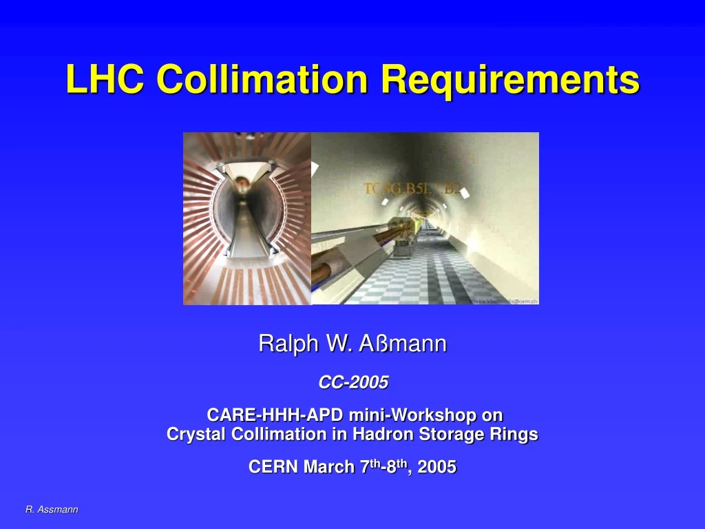
LHC Collimation Requirements. Ralph W. A ß mann CC-2005 CARE-HHH-APD mini-Workshop on Crystal Collimation in Hadron Storage Rings CERN March 7 th -8 th , 2005. Outline. Why do we need beam cleaning for the LHC? Phase 1 cleaning and collimation system

E N D
LHC Collimation Requirements Ralph W. Aßmann CC-2005 CARE-HHH-APD mini-Workshop onCrystal Collimation in Hadron Storage Rings CERN March 7th-8th, 2005
Outline • Why do we need beam cleaning for the LHC? • Phase 1 cleaning and collimation system • Crystals for phase 2 of LHC collimation? • Conclusions
Factor ~ 200 Why do we need beam cleaning for the LHC? The LHC machine: Physics High luminosity at high energy: Great discovery potential! Accelerator design Handling of ultra-intense beams in a super-conducting environment: Great risk of quenching & damage! Control losses ~ 1000 times better than present state-of-the-art!
Running at the Quench Limit Quench threshold (7.6 ×10⁶ p/m/s @ 7 TeV) Allowed intensity Illustration of LHC dipole in tunnel Cleaning inefficiency Leakage rate = Number of escaping p (>10s) Number of impacting p (6s) Beam lifetime (e.g. 0.2 h minimum) Dilution length (50 m) Collimation performance can limit the intensity and therefore LHC luminosity. Efficiency should be better than 99.9%.
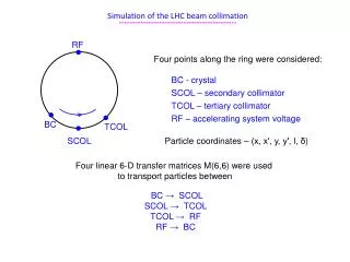
Two-Stage Cleaning Beam propagation Core Diffusion processes 1 nm/turn Primary halo (p) Secondary halo p p p Tertiary halo Impact parameter ≤ 1 mm p e Primary collimator p Secondary collimator Shower e Sensitive equipment Shower
Beam Loss Specification • The collimation system was designed based on the following assumptions on loss rates: • Loss rates based on experience. Not too conservative: Peak loss at 7 TeV is 1% of beam in 10s! • Supported by external review, taking into account Tevatron, HERA and RHIC experience!
Allowable Intensity in the LHC For peak loss rates: 0.1 h lifetime at injection 200 kW 5% loss in first s of ramp 1 MW 0.2 h lifetime in collision 500 kW
Outline • Why do we need beam cleaning for the LHC? • Phase 1 cleaning and collimation system • Crystals for phase 2 of LHC collimation? • Conclusions
Phase 1 cleaning and collimation system • LHC collimation system has been redesigned in the last two years! • In view of tight LHC boundary conditions the following decisions were taken: • Rely on proven multi-stage cleaning process. • Rely on conventional collimators with advanced features for the start-up of the LHC (phase 1). • Integrate space reservations into the LHC layout for later test/installation (phase 2) of advanced concepts for cleaning (advanced collimators, crystals, …) • Layout optimized for phase 1 of collimation.
The LHC Cleaning Insertions Two warm LHC insertions dedicated to cleaning: IR3 Momentum cleaning IR7 Betatron cleaning
Phase 1: From halo tracking to losses M. Brugger et al Where does the energy go Fluka
Energy flux and dose in IR7 K. Tsoulou et al IP UJ76 RR73 RR77 Flux (cm-2/y) 4 orders of magnitude NoAbsorbers A6vC6Eh6v Absorbers beam1 beam2 A6v E6v C6h E6v A6v C6h 0.1 MGy/y Dose (Gy/y) Mean values ± 2m horizontally and ± 1m vertically.
3% , 2.6 kW 7% , 7 kW Q7L Q7R PRIM SEC ABS F’wd leakage 1%, 1 kW Side leakage 20%, 19 kW VAC 8%, 7kW Warm Magnets 60%, 54 KW Power flow IR3, t = 1h , Ptot = 90kW • Need active and passive absorbers to limit load on auxiliary systems • Consequences for vacuum ... J.B. Jeanneret, I. Baishev
The LHC phase 1 collimator Beam passage for small collimator gap with RF contacts for guiding image currents Designed for maximum robustness: Advanced CC jaws with water cooling! Vacuum tank with two jaws installed
C-C jaw TED Dump C jaw Robustness Test with Beam Take: … and hit each jaw 5 times! 450 GeV 3 1013 p 2 MJ 0.7 x 1.2 mm2 equivalent Full Tevatron beam ½ kg TNT C-C (left) and C (right) jaws after impact No sign of any damage! Required robustness was demonstrated!
Damage Limits in Hardware Design • Danger to regular machine equipmentandmetallic absorbers: • Above 1e12 p at injection: 4e-3 of beam • Above 5e9 p at 7 TeV: 2e-5 of beam • Danger to C-C collimators/absorbers: • Above 3e13 p at injection: 10% of beam • Above 8e11 p at 7 TeV: 3e-3 of beam • Maximum allowed loss rates at collimators (goal): • 100 kW continuously. • 500 kW for 10 s (1% of beam lost in 10s). • 1 MW for 1 s. Crystals?
Impedance Limit for Movable Devices • Collimators and absorbers are close to beam: A resistive wall impedance is induced (gap size depends on b*)! • C-C material has reduced electrical conductivity (price to pay for a robust system). Fix with phase 2 advanced collimators. • Increase from collimators (nominal settings) for the imaginary part of the effective vertical impedance: • 8 kHz: factor 3 for injectionfactor 69 for 7 TeV • 20 kHz: factor 3 for injectionfactor 145 for 7 TeV • Large increase in impedance must be actively counteracted by transverse feedback and octupoles!
Outline • Why do we need beam cleaning for the LHC? • Phase 1 cleaning and collimation system • Crystals for phase 2 of LHC collimation? • Conclusions
Crystals for phase 2 of LHC collimation? Requirements for phase 2 of LHC collimation: • Improve cleaning efficiency! • Reduce collimator-induced impedance! • Maintain robustness and operational reliability! Any solution that helps in these goals is very welcome! We can also imagine a combination of different technologies! Can crystals help to achieve the phase 2 goals?
Two-Stage “Conventional” Cleaning Beam propagation Core Diffusion processes 1 nm/turn Primary halo (p) Secondary halo p p p Tertiary halo Impact parameter ≤ 1 mm p e Primary collimator p Secondary collimator Shower e Sensitive equipment Shower
A possible crystal collimation scheme? Beam propagation Core Diffusion processes 1 nm/turn Primary halo (p) Crystal Impact parameter ≤ 1 mm Shower p p Collimator-like object Absorber Sensitive equipment e Primary halo directly extracted! No secondary and tertiary halos!?
Scattering properties collimator Primary collimators (0.2m) give typical scattering angle of 2 mrad! Wide tails in strength of kick (deflect particles onto secondary collimators). If small deflection: Come back after some turns onto primary! What is the kick probability spectrum from the crystal?
Large deflections can be bad! Much stronger kick at injection!
Possible vertical collimator set-tings during in-jection, ramp and top energy: Afterb squeeze Smaller leakage rate with E increase!
Larger deflections at injection result in higher leakage rates (worse performance)! • Why? • System was optimized for top energy (7 TeV) scattering: Secondary collimators at optimal phase locations for 7 TeV kicks. • Similar system must be designed for crystals: Need to know… • How many absorbers? • Where to place them and for what energy? • How to handle collimation for different energies?
Conclusions • Crystals are an interesting advanced technology for phase 2 of LHC collimation. • To evaluate its benefit in detail the following information is required: • Damage limit of crystal for instantaneous shock beam impact (expect ~3MJ, 0.2×1.0 mm, 200 ns). • Damage limit of crystal for integrated dose (expect ~5×10¹⁶ p/year at 7 TeV). • Handling of crystal during normal operation: 500 kW power impact. Heating problems and need for cooling? • Probability spectrum for proton deflections (channeling and others) for energies from 450 GeV to 7 TeV. Include all effects down to 10-5 probability! • Number, opening (impedance) and locations of absorbers for extracted and scattered beam. How do the absorbers look like? • How to handle different LHC energies with crystals to ensure efficient cleaning from 450 GeV to 7 TeV? • Sensitivity to beam angle and angular spread? • Requirements for alignment and operational set-up (tolerances, time, …)?
Conclusions continued • Can we collect this information by the end of this workshop? • Detailed simulations must show the benefit of the crystal approach (include proton simulations, showers from crystals and absorbers). Done? • Experimental test is important. In the SPS: • What aspects can be tested in the SPS? • Channeling efficiency is no good measure of cleaning efficiency. E.g. if 95% is channeled: where do the 5% other particles go? We care at least on the 0.1% level! • Can we measure cleaning efficiency with crystals in the SPS? • How much time is required to establish crystal collimation? • When should such a test be done? Mandatory for 2006? • When could we arrive at a detailed evaluation for a crystal collimation system? • Space has been integrated into the LHC for a phase 2 upgrade!
Collimator Specification Driving criteria for material was robustness: Carbon-carbon Resistivity (7-25 mΩm)Short lead times 0.5 0.5