Download
1 / 34
340 likes | 345 Views
This article discusses the ILC as a Higgs factory, comparing linear and circular accelerators, staging and upgrading options, and the polarised positron production process.

E N D
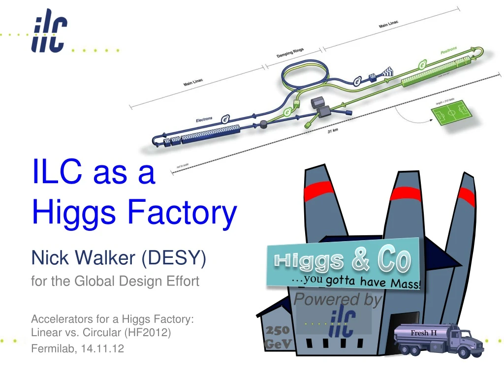
ILC as aHiggs Factory Higgs & Co …you gotta have Mass! Nick Walker (DESY) for the Global Design Effort Accelerators for a Higgs Factory:Linear vs. Circular (HF2012) Fermilab, 14.11.12 Powered by 250GeV
Known () Physics • ~125 GeV ‘that new boson’ • 125+91=216 GeV cm 250 GeV • 173 GeV Top quark • 2x173=346 GeV cm 350-400 GeV • Higgs self coupling (t-coupling) ??? • ≥ 500 CM (up to 650 ??) • TeV and beyond….? Staging / Upgrading
ILC in a Nutshell Polarised electron source Damping Rings Ring to Main Linac (RTML) (inc. bunch compressors) e+ Main Linac Beam Delivery System (BDS) & physics detectors Beam dump Polarised positronsource e- Main Linac not too scale
The ILC • 200-500 GeVEcme+e- collider L ~2×1034 cm-2s-1 • upgrade: ~1 TeV • SCRF Technology • 1.3GHz SCRF with 31.5 MV/m • 17,000 cavities • 1,700 cryomodules • 2×11 km linacs • Developed as a truly global collaboration • Global Design Effort – GDE • ~130 institutes • http://www.linearcollider.org
SCRF Linac Technology * site dependent Approximately 20 years of R&D worldwide Mature technology, overall design and cost
Global SCRF Technology TRIUMF, Canada ◉ IHEP, China STFC ◉ ◉ ◉ ◉ Cornell FNAL, ANL ◉ KEK, Japan ◉ JLAB DESY ◉ SLAC LAL Saclay ◉ ◉ ◉ INFN Milan ◉ BARC, RRCAT India GDE N. Walker (DESY/GDE)
Luminosity Scaling Law RF→beam power efficiency Beamstrahlung(physics) Vertical emittance
The Luminosity Issue • High Beam Power • Small IP verticalbeam size • High current (nb N) • High efficiency(PRF Pbeam) • Small emittance ey • strong focusing(small b*y, s*y ~ nm)
ILC Published Parameters Luminosity Upgrade Centre-of-mass independent: http://ilc-edmsdirect.desy.de/ilc-edmsdirect/item.jsp?edmsid=D00000000925325
ILC Published Parameters Centre-of-mass dependent: http://ilc-edmsdirect.desy.de/ilc-edmsdirect/item.jsp?edmsid=D00000000925325
ILC Published Parameters Centre-of-mass dependent: http://ilc-edmsdirect.desy.de/ilc-edmsdirect/item.jsp?edmsid=D00000000925325
ILC Published Parameters Centre-of-mass dependent: http://ilc-edmsdirect.desy.de/ilc-edmsdirect/item.jsp?edmsid=D00000000925325
Higgs Factory Centre-of-mass dependent: http://ilc-edmsdirect.desy.de/ilc-edmsdirect/item.jsp?edmsid=D00000000925325
Positron Production Polarised positronsource e- Main Linac not too scale
ILC Polarised-Positron Production e- linac Uses primary electron beam to generate ~30 MeV photons in a SC helical undulator Photons converted into e+e- pairs in “thin” titanium target Positron production yield dependent on e- beam energy (and therefore Ecm) e- to IP
Beam Delivery System e+ source e- BDS electron Beam Delivery System
Positron Yield Ebeam = 125 GeV 147m helical undulator(TDR baseline) design point yield margin Wei Gai (ANL) et al
Positron Yield for a LHF Ebeam = 125 GeV Recover yield by going to ~250 m of undulator yield margin Wei Gai (ANL) et al
10-Hz Mode • For TDR, we are required to have solutions down to Z-pole (~45 GeV beam) • ILC TDR assumes 10-Hz mode where • e- linac is pulsed at 10 Hz • first pulse @ 150 GeV to make positrons • second pulse @ Ecm/2 to make luminosity • Issues • DR damping time halved (extra cost and MW) • Beam dynamics in Main Linac (looks OK) • Additional beam lines and pulsed magnet systems • Additional AC power for elec linac 10-Hz mode • But for 500 GeV design, additional power already available • Not insignificant cost increase for a dedicated LHF
Conventional Source T. Omori et al, Nucl. Instrum.Meth.A 672(2012) 52-56
Higgs & Co …you gotta have Mass! Powered by 250GeV
TDR 500 GeV Baseline 15.4 km (site length ~31 km) 10.8 km 2.2 km 1.1 km 1.3 km Main Linac BDS e+ src IP bunch comp. Main Linac <Gcavity> = 31.5 MV/m Geff ≈ 22.7 MV/m (fill fact. = 0.72) central region Cost: 100% PAC: 161 MW
250 GeV Only 8.6 km (site length ~16 km) Half the linac Shorter BDS ½ RTML LRL ½ 10Hz mode e- linac 1.1 km 5.1 km 1.1 km 1.3 km Main Linac BDS e+ src IP bunch comp. central region
250 GeV staged (scenario 1) 15.4 km 5.1 km 1.1 km 2.2 km 1.3 km Main Linac BDS e+ src IP bunch comp. central region Half the linac Full-length BDS tunnel & vacuum (TeV) ½ BDS magnets (instrumentation, CF etc) ½ RTML LTL Extended tunnel/CFS already 500 GeV stage 10Hz mode e- linac
250 GeV staged (scenario 2) 15.4 km 5.1 km 1.1 km 2.2 km 1.3 km Main Linac BDS e+ src IP bunch comp. 125 GeV transport central region Half the linac Full-length BDS tunnel & vacuum (TeV) ½ BDS magnets (instrumentation, CF etc) 1 RTML LTL 5km 125 GeV transport line Extended tunnel/CFS already 500 GeV stage 10Hz mode e- linac quasi-adiabatic energy upgrade?
250 GeV CM (as first stage) Relative to TDR 500 GeV baseline (1312 bunches) Two stage compressor (5-15 GeV) Half linacs solution G = 31.5 MV/m
250 GeV CM (as first stage) Relative to TDR 500 GeV baseline (1312 bunches) Two stage compressor (5-15 GeV) POSITRON linac straightforward ~50% ML linac cost (cryomodules, klystrons, cryo etc.) ~50% ML AC power Half linacs solution G = 31.5 MV/m
250 GeV CM (as first stage) Relative to TDR 500 GeV baseline (1312 bunches) Two stage compressor (5-15 GeV) POSITRON linac straightforward ~50% ML linac cost (cryomodules, klystrons, cryo etc.) ~50% ML AC power Half linacs solution G = 31.5 MV/m ELECTRON linac needs 10Hz mode for e+ production DE = 135 GeV instead of 110 GeV (+25 GeV) ~57% ML linac cost (cryomodules, klystrons etc) 10Hz needs (1/2 linac × 10Hz/5Hz): 100% ML AC power (1/2 linac × 10Hz/5Hz) 80% cryo cost (50% static + 100% dynamic)
250 GeV CM (as first stage) Relative to TDR 500 GeV baseline (1312 bunches) Two stage compressor (5-15 GeV) POSITRON linac straightforward ~50% ML linac cost (cryomodules, klystrons, cryo etc.) ~50% ML AC power Half linacs solution G = 31.5 MV/m ELECTRON linac needs 10Hz mode for e+ production DE = 135 GeV instead of 110 GeV (+25 GeV) ~57% ML linac cost (cryomodules, klystrons etc) 10Hz needs (1/2 linac × 10Hz/5Hz): 100% ML AC power (1/2 linac × 10Hz/5Hz) 80% cryo cost (50% static + 100% dynamic) Total Main Linac infrastructure Linac components: 50% Cryogenics: 65% RF AC power 75%
Summary Warning! Approximate Scaling Only! Highly likely to change
Schedule for 500 GeV Machine Cost Review
MDI (Detector Hall) 2 Detectors in push-pull configuration Detector construction: 9 years (can be shorter?)
Central Region Damping Rings detector e+ main beam dump RTML return line e- BDS muon shield e+ source e- BDS Central region, detector hall (and detector) are schedule drivers Possible reduction for 250 GeV machine is 12-18 months (out of 10 years)
Summary • ILC (500 GeV) machine already “contains” a light Higgs factory • Luminosity: 7.5×1033 cm-2 s-1 • (Possible to upgrade by factor 2) • Standalone machine for LHF • reduced cost to ~65% of 500 GeV machine • PAC~ 100 MW • reduces schedule by 12-18 months(perhaps a little more) • Only really makes sense as part of a first-stage machine • scope of complete project still ~500 GeV • TeV upgrade remains optional