Download
1 / 15
150 likes | 277 Views
HIFI Critical Design Review. ICU AIV Planning and Implementation Renato Orfei Riccardo Cerulli Anna Maria Di Giorgio Sergio Molinari Scige’ John Liu’ IFSI-CNR. Assembly, Integration and Test Flow. HIFI ICU in house acceptance/tests procedure: step 1.

E N D
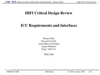
HIFI Critical Design Review ICU AIV Planning and Implementation Renato Orfei Riccardo Cerulli Anna Maria Di Giorgio Sergio Molinari Scige’ John Liu’ IFSI-CNR
HIFI ICU in house acceptance/tests procedure: step 1 Preliminary H/W acceptance tests will be executed at CGS premises 1 week before the boards delivery to IFSI: - H/W electrical and functional tests. - EPROM boot and emergency software tests The interfaces tests will be carried out by using IFSI in house developed simple S/Ss simulators and the CDMS simulator SW provided by the Consortia. Boards from contractor Assembly with cabling and connectors CDMS simulator HW/SW Integration tests A preliminary set of integrated H/W and S/W tests will be carried out by using the same simulators used for the boards acceptance. S/S simulator
HIFI ICU in house acceptance/tests procedure: step 2 Objective of these tests is to verify the specification and interface requirements. The following tests categories will be defined in the Test Plan: 1 Check-out of the CDMS I/F functions: - data link layer & physical layer conform to MIL-STD-1553B - Transfer Layer Protocol as in Appendix 9 of PS-ICD 2 Instrument Internal interfaces according to HIFI ICD. 3 OBS management functions, i.e.: - booting - S/W loading, dumping etc. - static functionality tests Functional and Performance Tests EGSE Subsystems simulators Assembly with mechanics TRR Env. Tests ICU Acceptance Tests Delivery Review
ICU in house Acceptance Test SET-UP STEP1: ACCEPTANCE OF BOARDS FROM CONTRACTOR CGS PC ICU CDMS SIMULATOR (Consortia) HIGH-SPEED I/F SIMULATORS BY IFSI LAN EXT. POWER SUPPLY (IFSI) LOW-SPEED I/F SIMULATOR BY IFSI S/W DEVELOPMENT TOOLS BY IFSI J-TAG LAN H/W TEST Equipment NOTE1: J-TAG & 21020 ICE FORESEEN FOR IN-HOUSE CODING/DEBUGGING NOTE2: HIFI S/S SIMULATORS BY MEANS OF DEDICATED PC CARD AND EXTERNAL H/W NOTE3: “LOW LEVEL” SOFTWARE USED TO TEST S/C AND S/Ss INTERFACES; PRELIMINARY S/W TESTS
ICU in house Acceptance Test SET-UP STEP2: EGSE+ CDMS simulator; IFSI S/Ss SIMULATORS PC EGSE + CDMS Simulator (Consortia) ICU LAN HIGH-SPEED I/F SIMULATORS BY IFSI/HIFI EXT. POWER SUPPLY (IFSI) S/W DEVELOPMENT TOOLS BY IFSI LOW-SPEED I/F SIMULATOR BY IFSI/HIFI J-TAG LAN H/W TEST Equipment PC NOTE 1: J-TAG & 21020 ICE FORESEEN FOR IN-HOUSE CODING/DEBUGGING NOTE 2: HIFI S/S SIMULATORS BY MEANS OF DEDICATED PC CARD AND EXTERNAL H/W NOTE 3: S/W MODIFIC./CORREC./UPGRADING VIA J-TAG; TRANSFER TO EGSE VIA LAN, FTP, DIR. SHARE
INSTRUMENT INTEGRATION TEST SET-UP STEP1: After Transport Validation/verification - On Site Acceptance ICU PC EGSE + CDMS Simulator (Consortia) LAN HIGH-SPEED I/F SIMULATORS BY IFSI EXT. POWER SUPPLY by HIFI S/W DEVELOPMENT TOOLS BY IFSI LOW-SPEED I/F SIMULATOR BY IFSI LAN H/W TEST Equipment PC NOTE1: ICU MECHANICAL BOX CLOSED; BOX ACCESSIBLE ONLY THROUGH CONNECTORS NOTE2: S/W MODIFICATIONS/CORRECTIONS/UPGRADING VIA S/W DEVELOPM. TOOLS, TRANSFER TO EGSE VIA LAN, FTP, DIR. SHARE.
INSTRUMENT INTEGRATION TEST SET-UP STEP2: S/C SIMULATION BY MEANS OF EGSE AND S/Ss SIMULATORS (OR ACTUAL S/Ss) PROVIDED BY HIFI ICU HIGH-SPEED I/F SIMULATORS OR ACTUAL SUBSYSTEMS BY HIFI EGSE + CDMS Simulator LAN EXT. POWER SUPPLY by HIFI LOW-SPEED I/F SIMULATOR OR ACTUAL SUBSYSTEMS BY HIFI S/W DEVELOPMENT TOOL PC-SIGMA 2000 CARD BY IFSI LAN H/W TEST Equipment PC NOTE1: S/W MODIFICATIONS/CORRECTIONS/UPGRADING VIA S/W DEVELOPM: TOOLS; TRANSFER TO EGSE VIA LAN, FTP, DIR. SHARE. NOTE2: RTA OF THE RESULTS OBTAINED, WHEN POSSIBLE, WITH EGSE TOOLS.
MODEL Facility Requirements AVM ·Random and Sine mechanical test facilities (NA). ·Shock facility (NA). ·Thermal Vacuum test (NA) ·EMC: only conducted Emission Differential and Common Mode EQM Qualification Levels · Random and Sine mechanical test facilities (Alenia Spazio, L’Aquila (TBC)) ·Shock facility (Alenia Spazio, L’Aquila (TBC)) ·Thermal Vacuum test (IFSI TBC) ·EMC tests (Flextronics (ex Siemens) l’Aquila (TBC)) FM Acceptance Levels ·Random and Sine mechanical test facilities (Alenia Spazio, L’Aquila (TBC)) ·Shock facility (Alenia Spazio, L’Aquila (TBC)) ·Thermal Vacuum test (IFSI TBC) ·EMC tests (Flextronics (ex Siemens) l’Aquila (TBC)) FS ·As FM Test Facilities Requirements
ICU Test Plan - Test types: • 1) Metrological Tests (Interface Drawing Tests) • 2) Electrical tests:The different models AVM, EQM, FM and FS are specified to be electrically identical as far as the hardware interfaces with S/C and subsystems are concerned and functionally identical. The AVM will contain only one computer unit while the remaining models will be fully hardware redundant containing two computer units. • Voltage levels (+ Noise) for the ICU and for the FCU • DC/DC Converters efficiency (ICU and FCU) • Inrush current • Conducted emission and susceptibility on power and signal lines* • Common mode tests on power and signal lines* • Total power drain • Interface signal timing to/from S/C • Pin functions • Insulation and Grounding • 3) Performance Tests:The purpose is to exercise all hardware and software functions, including non destructive negative conditions, to verify the correct response of the equipment. • The tests shall be carried-out in normal environmental conditions, in marginal power supply conditions, during thermal vacuum test steps and after vibrations. All electrical tests will be carried out, when possible, at IFSI. * EMC/EMI environmental tests will be performed at a Flextronic (TBC) facility.
ICU Test Plan - Test types: • 4) Vibration tests: The tests shall demonstrate the capability of the ICU to withstand the stress induced by vibrations during the launch phase without degradation of performances. The resonance research will indicate the frequencies at which the maximum stresses will be induced by the vibrations to the structure and to all devices internal to the box. • a low level sinusoidal vibration for resonance frequencies research • sinusoidal vibration at qualification level for the EQM or at acceptance levels for the FM and FS • random vibration at qualification level for the EQM or at acceptance levels for the FM and FS • The Vibration Tests will be performed at a still TBC facility.. • 5) Thermal Vacuum Tests: their purpose isto check that: • there is sufficient thermal dissipation inside the unit • no outgassing materials are used • no assembly defects exist as they are emphasised by the combined effects of thermal cycling and heat dissipation. • The Thermal Vacuum Tests will be performed at IFSI or at a still TBD facility. Meaningful tests require the interconnection with the HIFI subsystems and the EGSE in order to allow thorough performance testing checks to be carried out as required during thermal cycling and/or soaking phases.
ICU Test Plan - Test types: • 6) EMC/EMI Tests: their purpose isto verify the compatibility of the instrument subsystems with the electromagnetic environment of Herschel. For reasonable results these tests should be carried-out together with: the HIFI subsystems or the S/S simulators, the HIFI EGSE or at instrument integrated level. • conducted emission and susceptibility on power lines and Common Mode on signal lines • radiated emission and susceptibility • radiated ESD susceptibility tests • conducted ESD susceptibility tests • 7) Functional Tests: their purpose isto verify the full ICU OBS functionalities in all the instrument operating modes, including the autonomous functions. • The OBS will be tested against the requirements listed in the OBS URD. The main OBS functionalities to be tested are: • Verify the switch-on procedure implementation • Verify the TC handling • Verify the commanding implementation (static; the dynamic tests will be part of the performance tests); • Verify the correct TM generation in all instrument modes • Verify the correct implementation of autonomous functions • Verify the implementation of the time synchronisation