Download
1 / 19
890 likes | 2.18k Views
Heat Sink Selection. Thermal Management of Electronics San Jos é State University Mechanical Engineering Department. Heat Sink Categories. Passive Heat Sinks Used in natural convection applications or in applications where heat dissipation is not dependent on designated supply of air flows

E N D
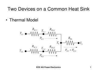
Heat Sink Selection Thermal Management of Electronics San José State University Mechanical Engineering Department
Heat Sink Categories • Passive Heat Sinks • Used in natural convection applications or in applications where heat dissipation is not dependent on designated supply of air flows • Height at heat input: ~10mm to large • Normal load limit: 5-50 W • Cost range at 10,000 pieces: $0.50-$10.00 http://www.dansdata.com/images/c3ezra/viasink220.jpg http://www.amatteroffax.com/images/inventoryimages/691916.JPG
Heat Sink Categories • Semi-Active Heat Sinks • Leverage off of existing fans in the system • Usually a passive heat sink set in front of a fan to produce impingement or vertical flow • Height at heat input: ~10mm • Normal load limit: 15-25 W • Cost range at 10,000 pieces: $5.00-$10.00
Heat Sink Categories • Active Heat Sinks • Fans are designated for its own use • Reliability is dependent on moving parts • Height at heat input: 35-80mm • Normal load limit: 10-160W • Cost range at 10,000 pieces: $10.00-$20.00 • One big negative: if your fan dies, you need to replace the entire unit http://cache-www.intel.com/cd/00/00/14/97/149748_149748.jpg http://www.newegg.com/Product/ProductList.asp?Brand=1647&N=2010110062+50001647&Submit=ENE&Manufactory=1647&SubCategory=62
Heat Sink Types • Stampings • Copper or aluminum sheets stamped into desired shapes • Low cost solution to low density thermal problems • Casting • High density aluminum or copper/bronze pin fins are produced with sand, lost core, or die casting (May or may not be vacuum assisted) • Allows for maximum performance with impingement cooling • More expensive but can make odd shapes • Al alloys used have lower conductivity than Al alloys used for extrusions
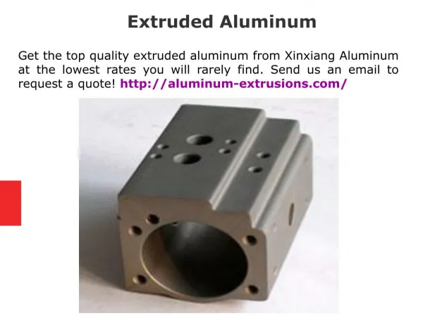
Heat Sink Types • Extrusions • Allows for the formation of elaborate 2-D shapes capable of dissipating large heat loads • Cross-cutting to produce rectangular pins may increase performance by 10-20% but the extrusion rate will be slower • Design limits are usually set by • Fin height-to-gap aspect ratio • Minimum fin thickness-to-height • Maximum base to fin thickness
Heat Sink Types • Bonded/Fabricated Fins • Thermally conductive aluminum filled epoxy is used to bond planar fins on a grooved extrusion plate • Greater fin height-to-gap aspect ratio is achieved with this method (~20-40) • Cooling capacity is increased without increasing volume requirements • But epoxy has a much lower thermal conductivity, acting as an increased resistance.
Heat Sink Types • Folded Fins • Aluminum or copper sheet metal is folded into fins and then attached to a base plate or directly to the heat surface via brazing or epoxying • Due to the availability and fin efficiency folded fins are not suitable for high profile heat sinks • Allows for the fabrication of high performance heat sinks when extrusion or bonded fins are unacceptable
Heat Sink Geometries • Rectangular fins have better performance than square fins, whose back edges have poor air flow past them. • Rectangular fins also have better performance than round fins; however, pressure drop is also higher for rectangular fins. • Round fins are good if you don’t know which direction your airflow will be from or if airflow may not be straight through the heat sink (it’s omni-directional). • For natural convection/radiation, solid black anodized fins mounted in a vertical direction tend to work best.
Heat Sink Materials and Finishes • Aluminum (6063 or 6061) is most common, followed by copper (which is 4-6x more expensive, 3x as heavy, by has 2x the conductivity) • It is difficult to alter the surface of copper to improve radiation. • External finish of aluminum is usually anodize or chromate of various colors.
Design Considerations • The following cases always increase thermal performance - True or False? • Longer fin heights • Longer heat sinks in the direction of air flow • Increased number of fins
Design considerations • All of the cases are false • Longer fin heights mean increased surface area but with a fixed volumetric flow rate performance may actually decrease with fin height • Longer heat sinks in the direction of flow and more fins both mean increased surface area but both have adverse affects on pressure drops and flow bypass, and the average heat transfer coefficient goes down
Flow Bypass • Flow bypass occurs when the flow duct is larger than the cross sectional dimensions of the heat sink • Velocity of the approaching fluid may be much greater than the velocity through the channels • Most commonly occurs with semi-active heat sinks
Flow Bypass • The amount of flow bypass will be greatly dependent on the cross sectional geometry and the pressure drop across the heat sink Lee, S. “Optimum Design and Selection of Heat Sinks”. Pg. 815
Radiation in Heat Sinks • Radiation in heat sinks is usually accounted for with an open-sided U-shaped channel • 3 surfaces are considered opaque and the other 3 are transparent • The 3 opaque surfaces should be analyzed for the amount of energy that is emitted, absorbed, and reflected Kraus, A. Pg. 292
Thermal Performance Graphs • Provided to show the thermal performance of a heat sink under ideal natural and force convection conditions • Ideal conditions mean: • Mounted to a heat source the same size of the heat sink • At sea level • Mounted with the fins in the direction of air flow • The heat sink is painted or anodized black • Zero Flow Bypass
Thermal Performance Graphs • Natural Convection Curve • Extends from the lower left to the upper right • Temperature rise vs. Q • Forced Convection Curve • Extends fro them upper left to the lower right • Thermal resistance versus air velocity Lee, S. How to Select a Heat Sink. Pg. 5
Attachment Means • Clip to device • Clip to PCB • Snap-on stampings • Double-sided tapes • Solder or adhesives • Thermal interface resistance minimized using grease or pad and by making surfaces as flat as possible
References • Lee, Serri. “Optimum Design and Selection of Heat Sinks”. IEEE Transactions on Components, Packaging, and Manufacturing. Part A, Vol. 18, No. 4. December 1995. • Lee, Serri. How to Select a Heat Sink. Aavid Thermal Technologies, Inc. Laconia, New Hampshire. • Kraus, A. The Heat Sink Design Procedure. • Markstein, H., “Optimizing Heat Sink Performance”, Electronic Packaging and Production, v 35, n 10, Sept 1995, p. 38.